Hello
so made a project which includes a servo and a fan 2 push buttons one for the servo and one for the fan uSB connected providing 5v. At first made everything on one board (Arduino elego) prototype worked as expected yet when did the actual installation issues emerged. servo worked fine yet the fan was acting weird, namely, button which assigned for fan was activating both or sometimes it was activated by it self (servo) so decided to go with 2 boards
one for servo 2nd for the fan (110v), again prototype worked as expected yet actual installation has similar issues servo buton works ok but fan acts stupidly when pressing the fan button it turns on the servo as well,or the servo and the fan and starts workingf by it self goes on & off randomly without any action tken what so ever,
*by the way i placed a 10k resistor as a pullup for the fan but no resistor at all for the servo could it be the issue?
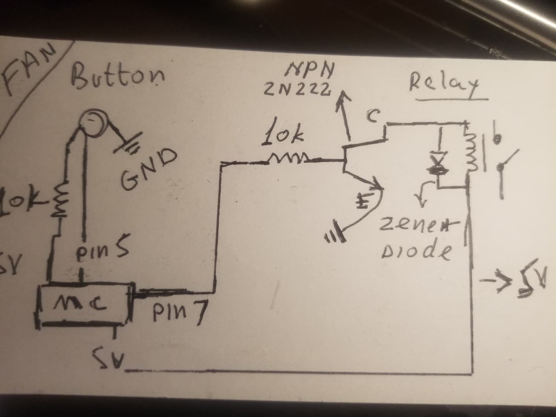
attaching sketch
Thanks in advance equipment
adafruit metro mini ( fan)
fan code
int LEDState=0; //fan
int LEDPin = 2; //fan
int buttonPin = 5;
int buttonNew;
int buttonOld=1;
int dt=100;

void setup() {
 // put your setup code here, to run once:

pinMode(LEDPin, OUTPUT);
pinMode(buttonPin, INPUT);

}

void loop() {
buttonNew=digitalRead(buttonPin);
if(buttonOld==0 && buttonNew==1){
 if (LEDState==0){
   digitalWrite(LEDPin,HIGH);
   LEDState=1;
 }
 else{
   digitalWrite(LEDPin, LOW);
   LEDState=0;
 }
}
buttonOld=buttonNew;
delay(dt);
}
~Servo
#include <Servo.h>

int posi = 50 ;       //position XXX changed so it attaches at the start point of sweep
int Servopin = 10 ;
int ServoDelay = 30 ;
Servo RedServo; //was coolServo XXXX

//these lines are new for the button cycle stuff
bool servoMustMove = false;
byte buttonPin = 3; //button from pin to ground

void setup()
{
  Serial.begin(9600);
  RedServo.write(posi); // XXX new so it attaches at the start point of sweep
  RedServo.attach(Servopin);
  pinMode(buttonPin, INPUT_PULLUP); //button from pin to ground
  Serial.println("setup done");
}

void loop()
{
  // the servo sweep stuff has been moved to a function servoSweep()
  if (!digitalRead(buttonPin)) servoMustMove = true; //! means not, this checks for button press
  if (servoMustMove) servoSweep();
}//loop

void servoSweep()
{
  for (posi = 50; posi <= 95; posi = posi + 3)  // angles ~ posotions  from 90 degrees to 50 degrees XXX lose the ;
  {
    //Serial.print("going up ");
    //Serial.println(posi);
    RedServo.write(posi);
    delay(ServoDelay);
  }

  delay(1500); //XXXX new, forgot it before

  for (posi = 95  ; posi >= 50; posi = posi - 2) // backwards  angles positions   from 50 back to 90 XXX lose the ;
  {
    //Serial.print("going down ");
    //Serial.println(posi);
    RedServo.write(posi);
    delay(ServoDelay);
  }

  servoMustMove = false; // XXXX new
}//servoSweep
This problem seems to me to be stemming from the fact that you do not have either a software or hardware debounce on your pushbutton for both sketches. You may want to refer to the Debounce sketch under examples > 02. Digital > Debounce (Arduino IDE)
I don't understand why you chose to write the position of the servo before attaching it. A servo's position is determined by the internal potentiometer and as such it doesn't matter where the arm is positioned on power on as the servo will always "know" where it is and as such where to go. You should simply attach the servo first and then write it to the position you want it to go (0-180deg).
This shouldn't be an issue because for the fan the 10K resistor is the hardware pullup while for the servo you defined the pinMode as INPUT_PULLUP (i.e the microcontroller will make the same connection for you internally). Either way if you define INPUT_PULLUP and still add a hardware pullup it really shouldn't affect much.
Consider also placing Serial.print lines after key sections of your code (such as when a HIGH is registered on the button) so you know when the button has been "pressed". That would help you eliminate the causes systematically.
As such I think your best bet is to try the Debounce sketch and also place a capacitor on the Servo Rail just in case your servo was being underpowered.
First things first..
it’s very unlikely you can power the relay from the Arduino.
Second, I can’t see how your button’s wired. It is a strange drawing.
I (think?) it’s basically correct, but what’s that resistor for on the left? Try looking at examples that use INPUT_PULLUP
Hello
button has 2 gangs gang one has TWO wires
wire one goes to 5v with a 10k resistor ( pull up)
wire II from same gang goes to a pin on a board
gang II wire goes GND
using NPN to power relay did the Math works but something's wrong
He is powering the relay using an NPN BJT. From the datasheet for the 2N2222 the max gain should be 300-ish so calculating the current through the base:
I_base = 4.4V / 10K ~ 0.5mA and thus I_CE should be about 150mA which should power the standard 5V Chinese relay (rated for 10A, 220VAC). However I would personally have used a MOSFET.
UPDATE I stand corrected I didn't notice the 5V was also originating from the MCU. As such the relay is being powered from the 5V of the MCU assuming no external power supply.
basically, one side of Usb adaptor comes out of a 110volt outlet the other side of the usb wire is cut and stripped and the 2 wires Hot (5v) and neutral are spliced and connected to 5 v and gnd of both boards
each board by it self works fine and seems like there's no power issue when both are connnected but it behaves in a weird way the button which is assigned for the fan turns on the fan and the servo as well or starts working on and off while i dont touch it at all
The "standard 5V Chinese relay" requires 70 to 90 mA of current. To saturate the transistor in order to minimise voltage loss and consequent heating, you drive it with one tenth to one twentieth of the collector current. Let's say about 5 mA and therefore a 1k base resistor.
Correct me if I'm wrong but I was thinking along the lines of finding out the "theoretical maximum" current (I_ce) that the BJT would be able to supply to the relay in response to the possibility that the relay was being underpowered (that was before I realized that OP could have been sourcing the 5V from the MCU itself instead of an external 5V supply). Hence my calculations.
Not sure what you intend here. If you wish to use a transistor as a power switch , you drive the base with between one tenth to one twentieth of the collector current in order to minimise voltage drop and consequent heating in the switching transistor. This is what you want to do when you drive a relay.
This is referred to as "saturating" the switching transistor. The HFe is not relevant to this.
Ok, gotcha now I believe the 1/10 - 20 I_be to I_ce ratio you are referring to is the rule of thumb for hard saturation of a BJT, because the hfe value of most transistors would be a lot larger than the hfe_sat value of 10/20.
I guess as @LarryD mentioned in #6 the best way to see if the BJT is saturated would be to for OP to check the voltage drop with a multimeter.