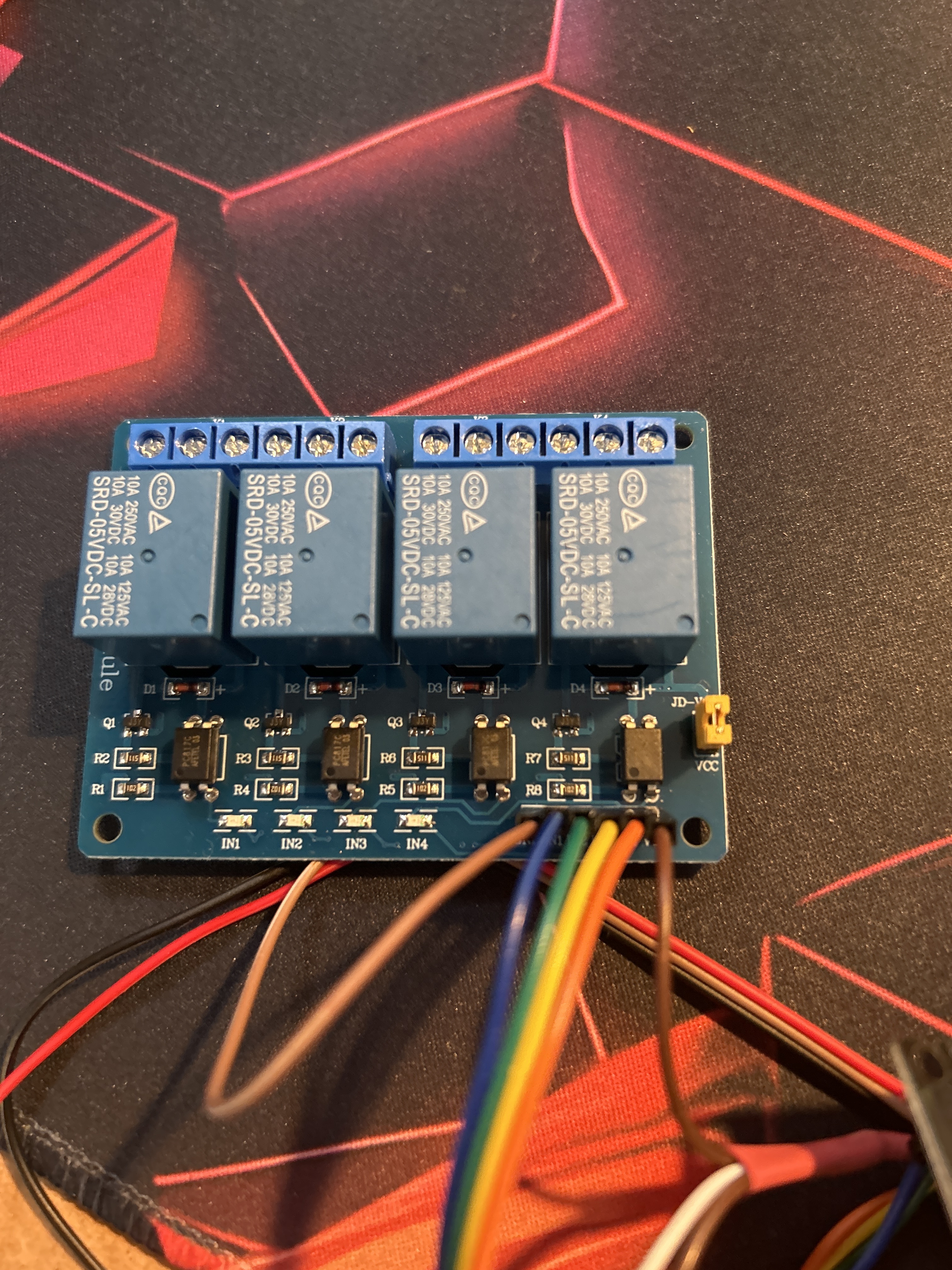
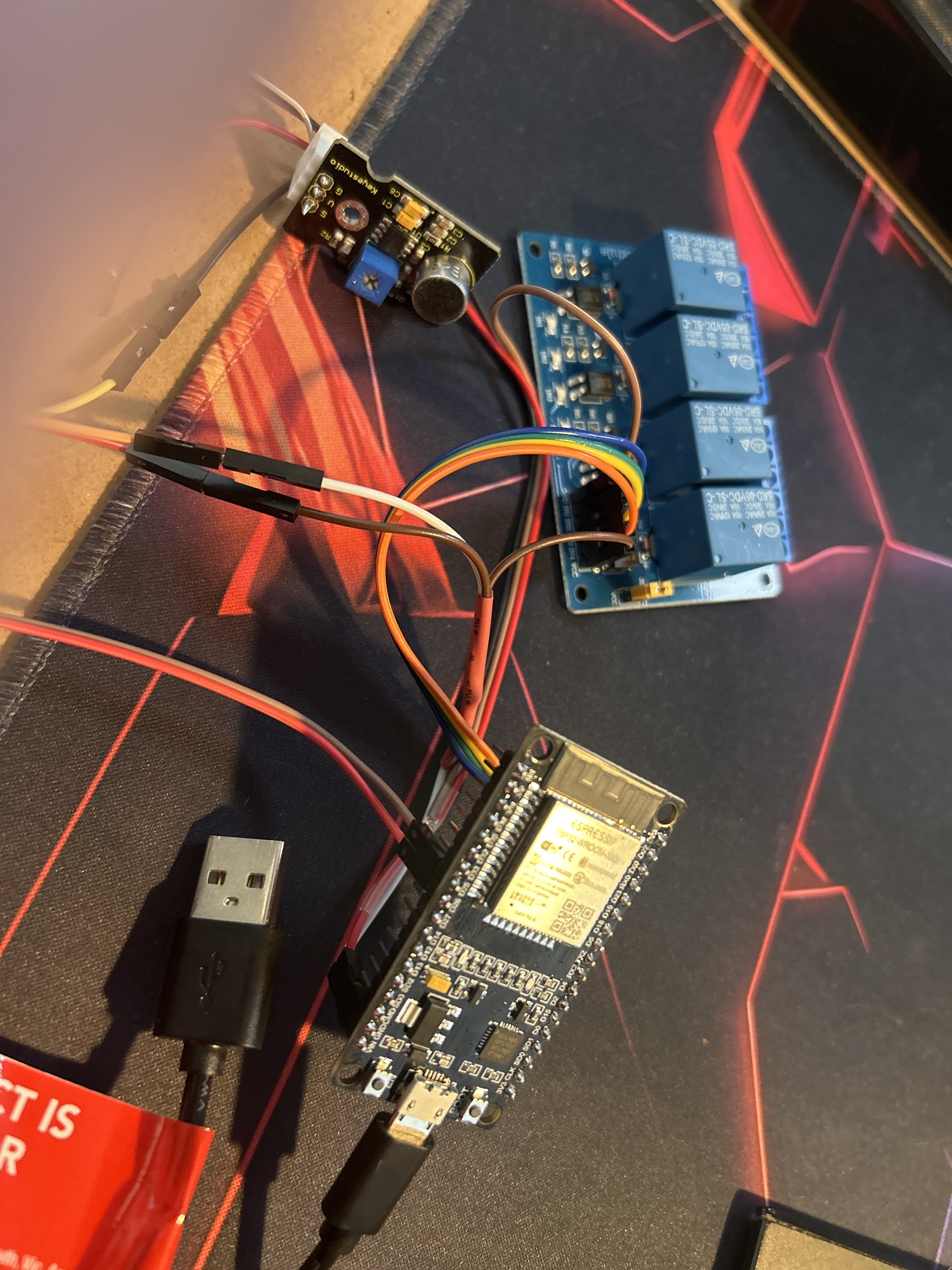
I have this really simple code for switching a relay on 3 seconds every time a sound sensor picks up a sound.
I don't know what is wrong but my relay seems to be doing the opposite and staying on and going for 3 seconds. I am assuming that when the relay LED is on the relay is on.
I am using and ESP32
Is there are way to get this working the way it should.
int relay1=19;//set up pin for Solenoid output (any Digital pin can be used)
int micsensorpin=26; //setup pin for input from Sensor D0
int micState;//set up a variable to hold info from D0 (HIGH or LOW)

void setup()
{
  Serial.begin(115200);
pinMode(relay1,OUTPUT);// set up the Solenoid pin to be an output
pinMode(micsensorpin,INPUT);//set up the sensor pin to be an input
digitalWrite(micsensorpin,LOW); //start with the sensor pin off
//digitalWrite(relay1,LOW); //start with the solenoid off
}

void loop()
{
micState=digitalRead(micsensorpin);//check if the mic sensor is on or off
if(micState==HIGH)// if the mic sensor is on, turn on the solenoid for 2 seconds
{
digitalWrite(relay1,HIGH);
Serial.println("sound heard");
delay(3000);
}
else
{
digitalWrite(relay1,LOW);
}
}
Extending @PaulRB's reply, you can use something like below near the beginning of the code
#define RELAY_ON LOW
When setting the relay on, use
digitalWrite(somePin, RELAY_ON);
and for switching it off
digitalWrite(somePin, !RELAY_ON);
This keeps it readable / makes the code easier to understand. If in future you use a different relay board where HIGH means on, simply change the first line to #define RELAY_ON HIGH.
Here is the new code that works using all of your valuable advice.
#define ON HIGH
#define OFF LOW

int relay1=19;//set up pin for Solenoid output (any Digital pin can be used)
int micsensorpin=26; //setup pin for input from Sensor D0
int micState;//set up a variable to hold info from D0 (HIGH or LOW)

void setup()
{
  Serial.begin(115200);
pinMode(relay1,OUTPUT);// set up the Solenoid pin to be an output
pinMode(micsensorpin,INPUT_PULLUP);//set up the sensor pin to be an input
//digitalWrite(micsensorpin,LOW); //start with the sensor pin off
digitalWrite(relay1,OFF); //start with the solenoid off
}

void loop()
{
micState=digitalRead(micsensorpin);//check if the mic sensor is on or off
if(micState==HIGH)// if the mic sensor is on, turn on the solenoid for 2 seconds
{
digitalWrite(relay1,ON);
Serial.println("sound heard");
delay(3000);
}
else
{
digitalWrite(relay1,OFF);
}
}
That's phase one and was good at getting me to understand the simple stuff. PHASE 2. So I applied the ON OFF definition and the INPUT_PULLUP. But it does not work on this code:
#include <DIYables_IRcontroller.h>

// Define relay pins (adjust according to your setup)
#define RELAY_1_PIN 18
#define RELAY_2_PIN 19
#define RELAY_3_PIN 21
#define RELAY_4_PIN 22

#define ON HIGH
#define OFF LOW

// Define digital microphone pin
#define SOUND_SENSOR_PIN 26 // Digital mic pin (adjust based on your connection)

// Define pin for IR receiver
#define IR_RECEIVER_PIN 25 // The Arduino pin connected to IR controller


// Create an instance of the IR receiver
DIYables_IRcontroller_21 irController(IR_RECEIVER_PIN, 200); // debounce time is 200ms

// Variable to store the currently selected relay
int currentRelay = -1;  // No relay selected initially

void setup() {
  Serial.begin(115200);

  // Initialize relay pins as OUTPUT and set them LOW (off)
  pinMode(RELAY_1_PIN, OUTPUT);
  pinMode(RELAY_2_PIN, OUTPUT);
  pinMode(RELAY_3_PIN, OUTPUT);
  pinMode(RELAY_4_PIN, OUTPUT);

  digitalWrite(RELAY_1_PIN, OFF);
  digitalWrite(RELAY_2_PIN, OFF);
  digitalWrite(RELAY_3_PIN, OFF);
  digitalWrite(RELAY_4_PIN, OFF);

  // Initialize the IR receiver
  irController.begin();
  Serial.println("IR receiver initialized");

  // Initialize digital mic pin
  pinMode(SOUND_SENSOR_PIN, INPUT_PULLUP);
  Serial.println("Sound sensor initialized");
}

void loop() {
  checkIRCommand(); // Continuously check for remote commands
  checkSoundAndTriggerRelay(); // Check sound and trigger appropriate relay
}

// Function to handle remote control commands
void checkIRCommand() {
  Key21 command = irController.getKey();
  if (command != Key21::NONE) {
    Serial.print("Received command: ");
    Serial.println((int)command); // Print the command received for debugging

    // Handle IR commands to engage the relays
    switch (command) {
      case Key21::KEY_1:
        armRelay(RELAY_1_PIN);  // Engage relay 1
        break;
      case Key21::KEY_2:
        armRelay(RELAY_2_PIN);  // Engage relay 2
        break;
      case Key21::KEY_3:
        armRelay(RELAY_3_PIN);  // Engage relay 3
        break;
      case Key21::KEY_4:
        armRelay(RELAY_4_PIN);  // Engage relay 4
        break;
      default:
        Serial.println("Unknown or unsupported command");
        break;
    }
  }
}

// Function to arm the selected relay
void armRelay(int relayPin) {
  // Turn off the previous relay if one was selected
  if (currentRelay != -1 && currentRelay != relayPin) {
    digitalWrite(currentRelay, OFF);
    Serial.print("Relay ");
    Serial.print(currentRelay);
    Serial.println(" turned OFF");
  }

  // Set the current relay to the newly selected one
  currentRelay = relayPin;
  Serial.print("Relay ");
  Serial.print(currentRelay);
  Serial.println(" armed, waiting for sound trigger");
}

// Function to check for sound and trigger the currently armed relay
void checkSoundAndTriggerRelay() {
  // Check if a sound is detected
  if (digitalRead(SOUND_SENSOR_PIN) == ON) {
    if (currentRelay != -1) {  // Ensure a relay is armed
      // Trigger the currently selected relay
      digitalWrite(currentRelay, ON);
      Serial.print("Sound detected! Relay ");
      Serial.print(currentRelay);
      Serial.println(" triggered ON");

      delay(400); // Relay stays on for 400ms

      // Turn off the relay after the delay
      digitalWrite(currentRelay, OFF);
      Serial.print("Relay ");
      Serial.print(currentRelay);
      Serial.println(" turned OFF after delay");
    }
  }

}
On the above code I have four relays which should all be OFF when I start. The IR buttons are used to select a relay. One of 4. but They all start ON. and like before do the opposite. i.e, go off when the sound triggers them instead of the other way round. To me the code looks OK.