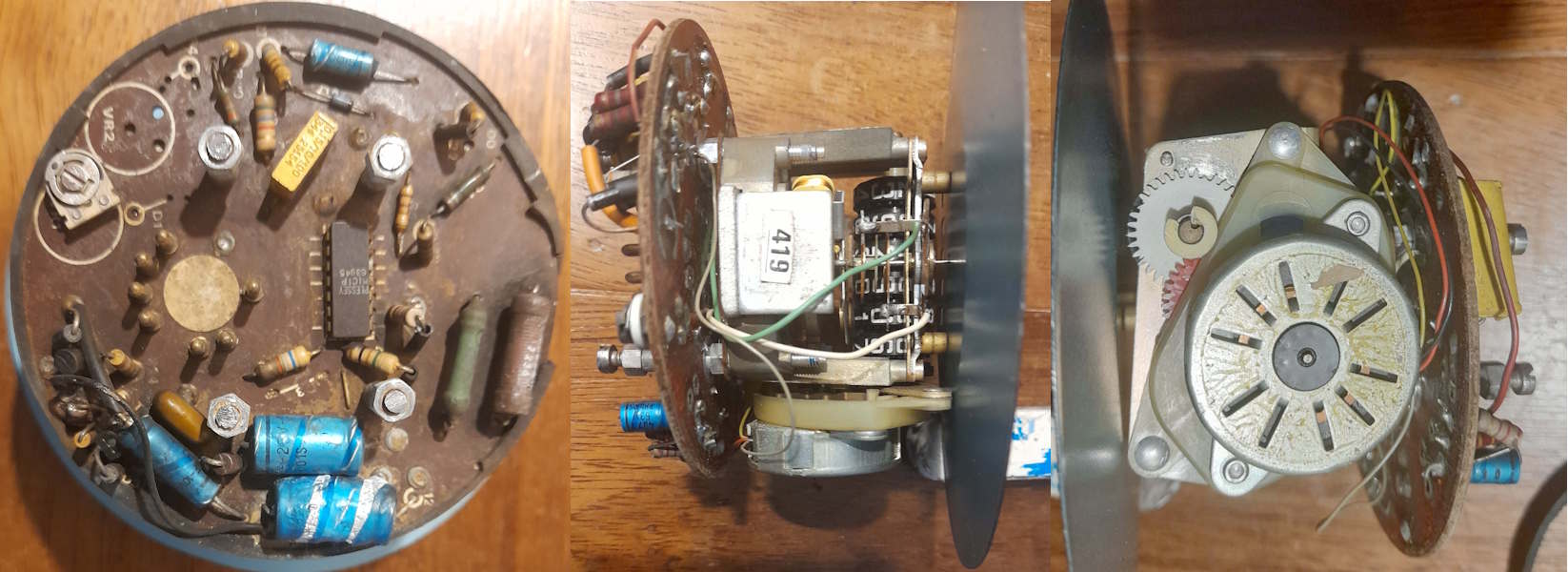
A friend has a heritage bus, but the speedo is broken. (photo)
the unit has an ammeter to show the speed, (you can see themoving coil above the "419" label)
and a 4 wire stepper motor to drive the mileometer.
Due to the age basically all the components are shot. Most of them are unidentifiable, especially the Plessey IC that I'm guessing is the stepper driver. No circuit diagram or component specs are available.
The bus HAS to have a working speedo & mileometer.
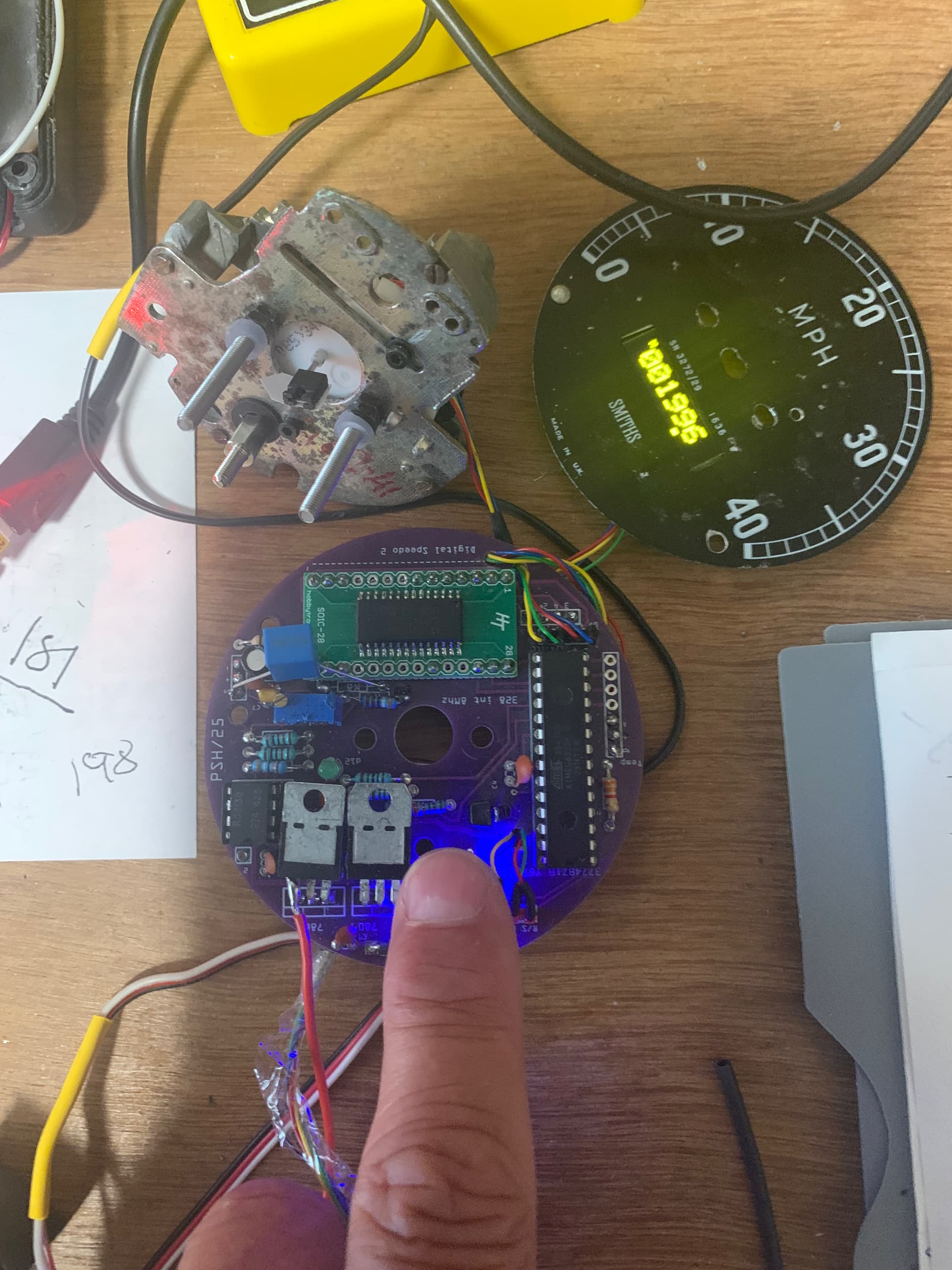
I'm wondering if its realistic to build a unit to drive the existing ammeter and stepper (so the unit retains its heritage appearance)
say with a nano or micro and a stepper driver.
and use the existing pulses from the sender unit to control the speed and mileage indication.
I know it would need to be calibrated, but I dont see that as a problem.
And the changes wouldnt show on an MOT.
I guess the main question is how to drive an unknown 4 wire stepper, so I'd start with that, and any advice on how to do so would be great - I've not worked with a stepper before.
Measuring the resistance of the coils likely gives some help.
Operating the stepoer at lowest possible currents ought to be safe.
One option could be to replace the stepper.
In all, build the functionality that's needed and skip old parts.
Well, driving the ammeter shouldn't be to difficult. You need to be able to control the current flowing through it i guess. Have you tried to see what it does using a variable power supply and a resistor to limit the current ? Have you actually measured the internal resistance of the meter to confirm that it actually is an ammeter ? Because in that case the internal resistance should be almost none, whereas i suspect that there is significant internal resistance.
Any idea what voltage the stepper motor is being driven with ? It might be easier to go a stepper motor of a known type and drive that instead.
Do you know what the pulse format is for the speedo. ..ie...shorter pulses the higher the speed..? I am guessing it has some sort of hall effect sensor as most speedo's are cable driven from that era
Driving the existing motor could be tricky as you will need to know its parameters like how fast it spins, how is it controlled. If you already know these then it wont be hard to setup an Arduino to control it
You could replace the motor with a known DC motor or stepper and drive it from the Arduino using the pulses to determine how fast the motor/stepper spins. You will need to make some sort of mount and adaptor, but a 3D printer is your friend here
Calibration is the easy bit, you just map the pulse reading value to speedo drive motor speed at a known speed
You could replace the motor with a known DC motor
The ammeter is a different problem, you would need a current sense module to read the current, but driving the meter is the hard bit as it relies on current value, not voltage. You could replace the ammeter with a small colour tft with an animated meter to replicate the old one
Yes it can be done but it will not be a simple project. Consider the following, it will help you design it so it survives. Valuable Resources for Automotive Electronics:
STMicroelectronics Application Note AN2689:
This application note provides guidelines on protecting automotive electronics from electrical hazards, focusing on design and component selection. Reading this will greatly enhance your understanding of automotive circuit protection. Read AN2689
Analog Devices: Automotive Electronics Design:
This article distills key insights into designing automotive electronics, offering practical advice for engineers. Read the article
Diodes Incorporated: Transient Voltage Suppression in Automotive:
Learn about techniques to protect automotive circuits from transient voltage, which is critical for ensuring reliable operation in harsh conditions. Read the article
AEC-100 Standards Webinar:
This webinar from Monolithic Power Systems provides a detailed overview of AEC standards, essential for understanding automotive electronics requirements. Watch the webinar
Understanding Automotive Electronics, An Engineering Perspective by William B. Ribbens:
This comprehensive book offers an in-depth look into automotive electronics from an engineering perspective, making it an invaluable resource. Access the book
These resources should provide a strong foundation for anyone involved in automotive electronics design. If you need further help or more resources, feel free to ask!
Thanks to all of you for such prompt and detailed replies, I'll try to answer your questions.
its 24V neg earth
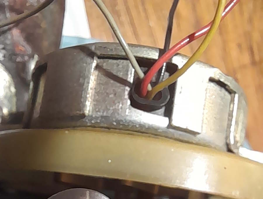
its 150 ohm; and the wires (red, black, yellow and summick pale) red and black ae connected together on the pcb, so yellow and (whatever the other color is - I'm color blind!) are the driven ends.
Replacing the mechanical parts isnt an option as I'd have to re-engineer the whole system.
well I hadnt - and this takes me back to my schooldays (early '60s)
its a moving coil galvanometer - 75 ohms, 25mA full scale. But driving that isnt an issue.
Thanks @gilshultz however this isnt intended for production, its a bodge to get the bus operational again as without a speedo it aint going anywhere. If it blows up all I'll have lost is a nano and a few bits.
The old speedos used in 1950:ies railcars are milli Amp meters.
If 25 mA gives full reading it points at 1.875 volt is needed. Maybe PWM would do, scaled somehow.
So a 24V PWM signal with around 23% duty cycle would be full scale. That's around analogWrite(60). Might be enough precision I think. One mile-per-hour per steps, if the bus's max speed is 60MPH.
It is possible to produce 16-bit PWM on ATMega328 using one of its timers. That should give more than enough precision.
I always want to start with the easy bit. My suspicion was that it would not be ammeter or a voltmeter, but more something that would be in between.
My next focus would be on the incoming pulse and how to interpret that, and does it still work. There is always the chance that it doesn't and that is the whole cause of the malfunction.
Still better to protect it as well as possible. A vehicle is a rather hostile environment for an MCU. What you will need is a stable power supply and as much galvanic isolation as you can create.
I used something as simple as putting the MCU and active parts in between 2 diodes, a fair size capacitor with quite a high voltage rating and then a linear regulator. The diodes preventing any reverse voltage rating and the capacitor soaking up the peaks. This is for a smart windscreen wiper relay. The relays are driven with NPN transistors, which are basically blocking any reverse voltage as well. For the incoming pulse you will need an opto-coupler, and you can probably drive the speedo will a simple filtered PWM signal if you can isolate it from the rest of the unit.
I’ve done a couple of these one using a gps module , one off a wheel sensor . In both cases I’ve used steppers to drive the pointer, but you can use your ammeter .
I would drive your ammeter off a voltage regulator ( say 12v) with the output , through a resistor , then your meter , then npn to ground .
Control the npn from a pwm output .
The resistor choosen to give max “mph” somewhere near max pwm (255) output .
Without the regulator changes in battery voltage will affect your readings .
The mileometer bit is harder , I cheated and just used an oled display . A lot use a mechanical rachet mechanism to move the mileometer , I could not find space to drive it .
Something similar to a fuel-gauge, Not to much current required, not to much resistance (in case of a fuel gauge that is also to prevent sparks in the tank), something fairly sturdy.
That sounds well worth trying , plus some basic fault finding .
The mileometer mechanism looks re usable.
If you can work out the circuit , you might be able to get it working - eg replacing the Plessey chip with something that would do the job or even a like for like replacement
Since the nano can source or sink 40mA why cant I just drive the galvanometer (25mA full scale) directly by PWM from a digital output - with a series resistor?
I dont need more than 1% precision so I'm happy with 8 bit.
I'm replacing the caps and the burnt out 75 ohm 5W resistors as soon as the parts arrive. However tracing and reconstructing the circuit from new isnt an option. Most of the resistors are so discolored I cant read the color codes, and cant assume the current values are what they were when new.
And replacing the plessey chip - M1C1P - well it was likely a special.
Plessey "In 1989, it was taken over ..."
There are also two transistors that (as yet I'm guessing) drive the motor coils. I'm trying to identify them: if all else fails I'll just test whether they are pnp or npn. Then maybe i can copy that bit of the circuit to drive the coils.
There is no regulator on the board although there seem to be a few zeners.
You may ask why not just unsolder and measure. All the wire ends are bent over so removing each one involves a lot of heat, and the tracks ...
I'm also hampered by my old eyes, and have to rely on macro photos to see the fine detail like faded part numbers.
75 Ohm. V = I * R, I = V / R, So 5 / 75 = 66mA. When you use PWM the voltage fluctuates between 5v & 0v, with a variable duty cycle. The maximum current that could flow is the moment that it is HIGH.
The coil will most likely reduce the maximum current, but you are already way over spec, and you should try not to be even close to spec.
I would take PWM output and filter it and drive a transistor with that.
5V 100% 25mA full scale = 200 ohms. So a series resistor of 200 - 75 ohms = 125 ohms is needed.
I'd probably allow a little headroom for calibrations, but say with a 100 ohm series R I max would be 30 mA.
Also the meter is caled to 80MPH, and these old buses are unlikely to exceed 60MPH = 20mA.
For filtering the existing circuit has a cap across the coil, but I think thats also for damping vibration.