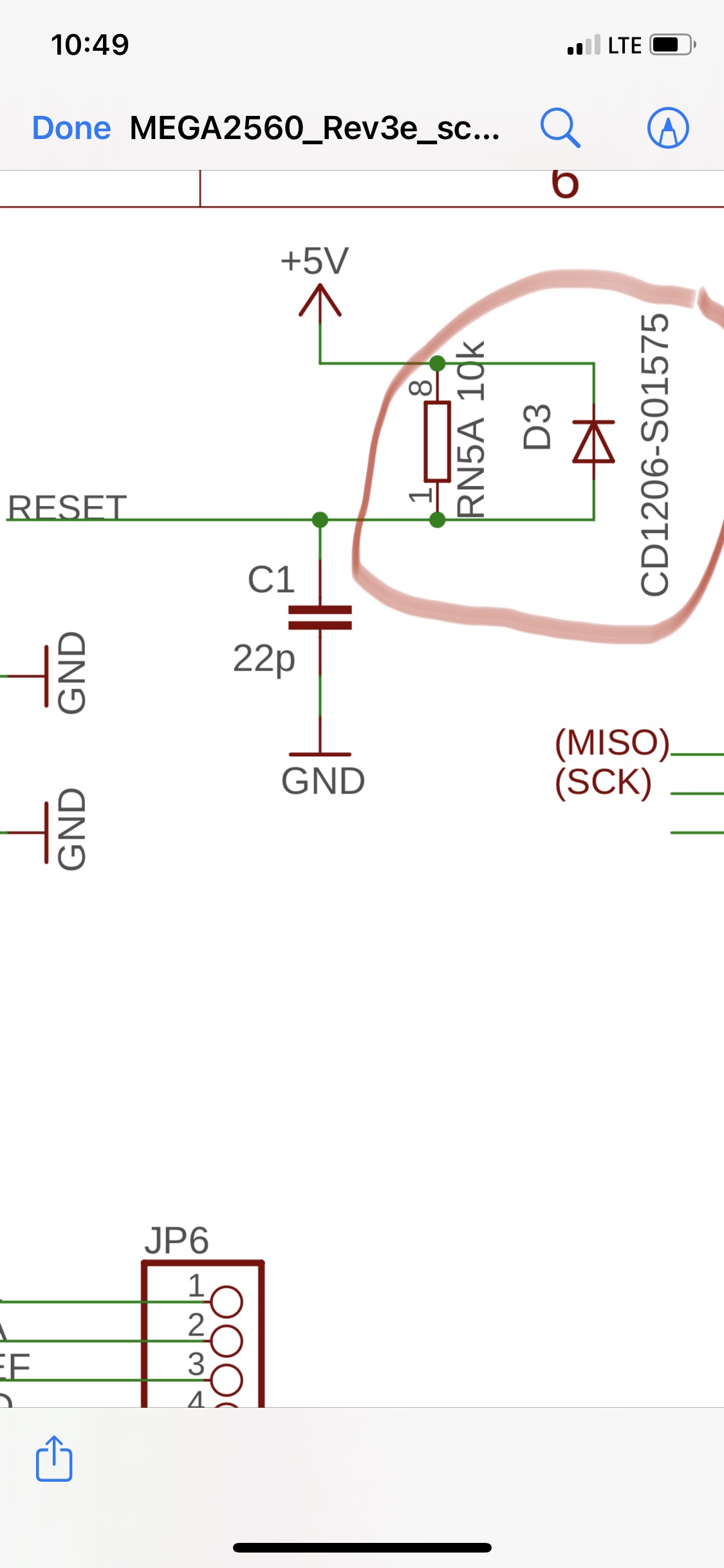
I am specifically inquiring about the Mega 2560 Rev 3 but I think this applies to the Uno Rev 3 and possibly many other devices. I have found plenty of documentation online for why the reset circuit has a pull-up resistor and diode… So that is not my question. My question is this. I see both these components in the electrical circuit diagram but I do not see both components in the Eagle files or in physical pictures of the board. I only see one component. I think it’s the diode. But it could be the resistor… either way… I don’t see both. Is it missing? Or are they both there and I just don’t understand? If they are both there… please show me where?
I just use a 10K pull-up resistor, not had any issues in over 10 years of using the ATMEGA328 & ATTINY85 chips.
If the reset pin has a input protection diode on the die , this diode will serve the same purpose as an external diode.
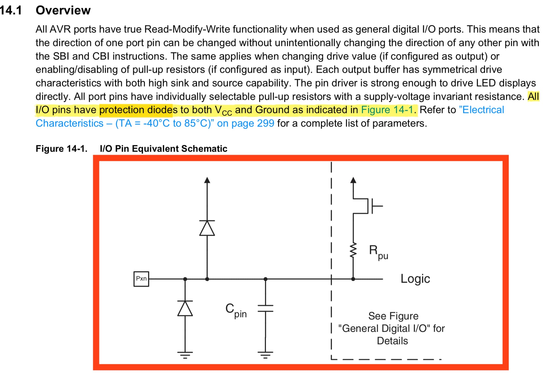
Which it doesn't if the uC supports high voktage programming as the diode would interfere with this. The equivalent diagram you posted therefore is not representative for the reset pin on such uc's!

That's it.
Btw, on occasion I have had problems if the external diode was not present. Particularly this was a board where power to the uC came from a Dc-Dc step down which apparently ramped up a bit erratically on startup. It was a problematic board for other (unrelated) reasons as well, but since that experience I always put the $0.01 diode on there just to be sure.
Looks like a series resistor is recommended too.
See 3.1 here:

The diode is there to quickly discharge the cap when the power is turned off.
So the full reset time is available again with a new bootup.
Without the diode the cap needs more time to discharge, and that could shorten reset time if the processor is started up again too quickly. Say with a dip in the supply.
The reset pin is AFAIK different (clamping) from other pins.
Leo..
Ah yes, so it clearly can/ will be held at a significant positive voltage even if/ when Vcc is zero. ![]()
Thank you for your input… however… none of these answers my question. As I said in my original post, I don’t need to know why it is or isn’t there… I don’t need to know why it is or isn’t needed… I have already found this information to my satisfaction… My question is simply this… when I look Arduino’s electrical schematic I see both the pull up resistor and the diode… But when I look at the eagle file I do not see both a pull-up resistor and a diode on the reset circuit… when I look at pictures of the board I do not see both either… my question is… Is this a mistake? Or are they there and I am just not seeing them? If they are both there… Where are they located?

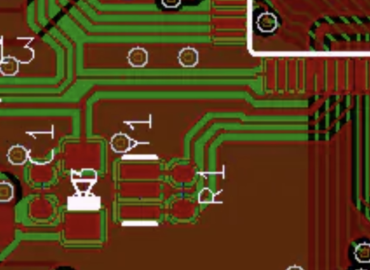
So I emailed Arduino yesterday before posting here… thought I might find the answer here more quickly… but Arduino emailed back today with the answer… So there are no missing components… the circuit diagram matches the pcb… Arduino pointed out that the viewer on their site allows you to select a component in the circuit diagram and then switch to pcb view or a 3d view of the board and it highlights it there… absolutely amazing… didn’t realize it was interactive like that…
It looks like you're referring to the DTR/RTS auto-reset circuit. The D2 diode is required to prevent a 10V pulse (created by C5 when DTR returns high) from inadvertently enabling high voltage programming of the ATmega328P. D2 clamps the reset signal to about 5.5V max.
UNO R3:

The history of the diode in the Uno/Mega reset circuitry is here: Regression between uno and uno R2 VALIDATED. HARDWARE PROBLEM CONFIRMED
This topic was automatically closed 180 days after the last reply. New replies are no longer allowed.