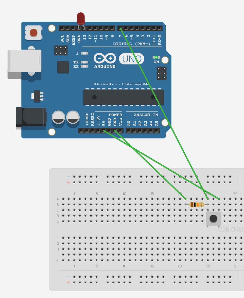
I'm doing a very simple beginner experiment. It's an LED in pin 13, a push-button on the breadboard. The circuit goes 5V -> switch 12 -> switch 22 -> pin 7 (INPUT) && [10k Resistor -> GND]
My question, is what is the function of the resistor? My guess originally is that it sends some current to pin7, otherwise it would all short to ground.
Why can't I send all the current to pin7 I noticed that when I removed the resistor and ground wire from the circuit and just went 5V -> switch -> pin7 the light is ALWAYS on even when the switch is open... can someone explain why this is?
Poor design copied from elsewhere no doubt.
Try this: button wired to connect 7 to Gnd when pressed.
Remove the LED, use the onboard LED that is driven from 13. At put a 270ohm resistor in series with the LED.
Then the code:
byte button = 7;
byte ledPin = 13;
void setup(){
pinMode (button, INPUT_PULLUP); // use the internal pullup so the pin is high when button is not pushed
pinMode (ledPin, OUTPUT);
}
void loop(){
if (digitalRead(button) == LOW){
// button is pressed
digitalWrite (ledPin, HIGH); // turn on LED
}
else {
digitalWrite (ledPin, LOW); // turn off LED
}
}
The pulldown resistor and connecting the pin to +5 when the switch is pressed is because beginners often think of a low pin as OFF and a high pin as ON; the 10K resistor bleeds off any voltage on the pin to hold it low when the switch is not connecting the pin to +5 when pressed.
In fact you can see how easy it is to think the other way: LOW is the active state, and HIGH is the inactive state.
Using the internal pullup also prevents miswires and shorting the 5V line to Gnd by accident and taking out the voltage regulator or causing other damage.
Basically if you have an input pin that is not connected to anything, its voltage could be anything
from 0 to 5V (for a 5V system).
This is called a floating input since CMOS circuitry takes effectively zero current (10^-12 A or
so in fact). A pull-up or pull-down resistor defines the voltage on the pin so it works reliably.
The ATmega microcontroller also has built-in pull-up resistors to save needing external resistors,
engaged by pinMode (pin, INPUT_PULLUP)
At room temperature CMOS inputs tend to be in the pA range. At 125C things are very different.
Datasheets give an upper bound on leakage across the temperature range and allowing for device
spread and future changes in manufacturing process.
Typical pins have capacitances of a few pF, and with a few pA leakage the resulting time-constants
are of the order of seconds(*) - so charging up an isolated pin by touching it to 5V will mean it jumps to 5V
and then decays back slowing to some rough resting voltage, superimposed with a lot of capacitive
pickup from nearby conductors (such as fingers!). This fairly easy to experiment with using an analog
pin
(*) 1 pA into 1 pF causes a voltage change of 1 V/s