Why do diagrams show a resistor between the sensor pin and the ground on the board rather than a resistor between the sensor pin and the board data input?
Is there no resistor between sensor and board due to the fact that these sensors act as resistors? Then, why do you need resistance to the ground on the board?
It's because resistors can't generate any voltage by themselves. Arduino requires a voltage input, so a resistive sensor can't generate by itself, any signal that the Arduino can read. The additional resistor provides a current, which when applied to the sensor resistor, produces a measurable voltage across the sensor, by Ohm's law E=IR where E is the output voltage, R is the sensor resistance, and I is the current injected by the auxiliary resistor.
That's a simplification, since actually the two resistors interact and are said to be in a "resistive divider", but I gave you the more fundamental story.
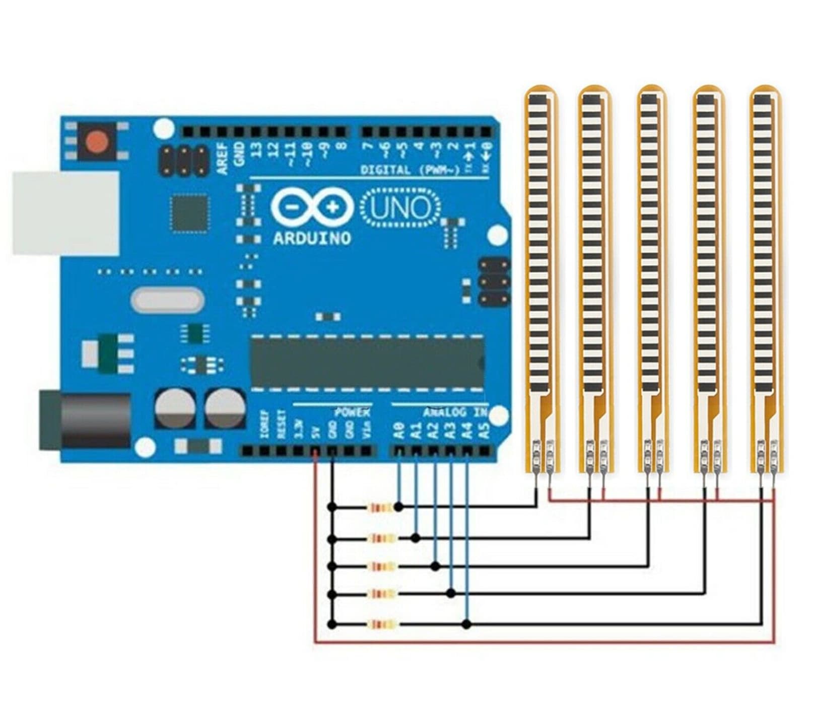
If you look at the circuit:
You'll see the voltage at the analog input depends on the ratio of the sensor resistance and fixed resistor - analog inputs take no current, they just sense voltage.
As analog inputs take no current adding a resistor in series with them achieves nothing as there is no voltage across it (such a resistor can provide protection in a fault situation though, which can be useful - for instance 1k to 10k kind of value might be useful for external inputs that might exceed 5V by accident).
Although an analog input normally takes no current, it has (normally reverse-biased) protection diodes to prevent the voltage going outside the range 0..Vcc, and these cannot handle large currents.