I'm having an issue with an RFID sensor and was wondering if anyone else has experienced this issue before/can think of a solution. First for some context: I am working on a project where I use RFID to control a magnetic lock. I've done it multiple times before, but I typically use 2 different power supplies. I use a 5V one for the Nano and a 12V one for the magnetic lock. I wanted to see if I could power both of these using a 12V power supply. I bought a 12V, 17A Meanwell power supply with 3 different voltage outputs to do this. I know that I can power the Nano through the Vin and GND pins with this. I had also read somewhere that giving the Nano 12V constantly would dissipate a lot of heat and could shorten the life of the board over time. To prevent this, I am using a buck converter to step the voltage down to about 8V.
Now for the problem. When I power the Nano through the USB, the whole project works perfectly, minus maglock because I'm just monitoring how the relay switches. The RFID sensor reads the chip, and the Nano drives the pin I have the relay attached to LOW and unlocks. There's some debugging lines in the code I am using that lets me see that everything is reading properly. However, if I power the Nano through the Vin with the power supply, the RFID sensor will not read the chip. Every LED lights up (relay, Arduino, RFID sensor, buck converter), and the serial monitor says the reader is initialized. If I switch it back to USB, works perfectly again.
I have tested the output pins with a multimeter to see if they are at 5V, and they are and are stable. I have tested the buck converter output, and it is at 8V. With a USB connection, I can place the chip on the reader and watch the voltage drop from 5V to 0V like I want it to. It won't drop when I do the same thing if it is hooked to a power supply. Has anyone had this issue before or have any suggestions as to what I might be doing incorrectly? Thanks.
Did you join the GNDs?
The RFID and relay are using one GND pin, and one GND pin is attached to the V out of the buck converter.
I guess my question was: Is there a direct link between the GND of the arduino and the GND of the other modules
Yes, there is a direct link.
Could you draw a quick circuit on how it’s all wired and powered?
Are your relay and mag lock protected with a diode / optocoupler?
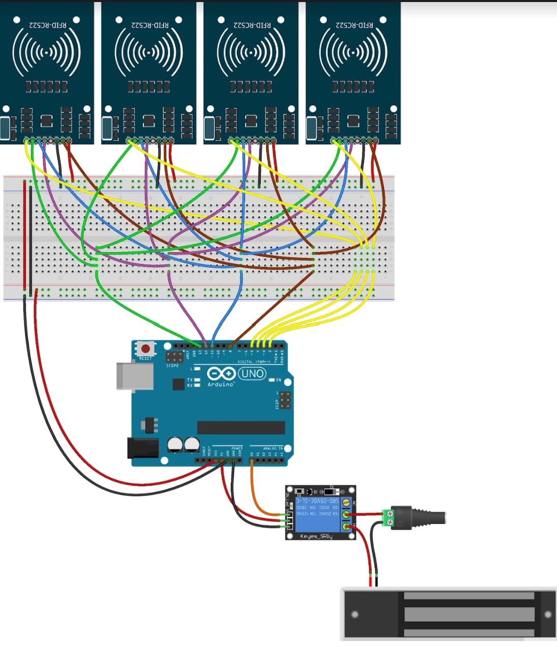
Here is the diagram I'm using. This is not my design. The differences in what I am doing as opposed to this diagram are that I am using a Nano, I only have one RFID sensor, and I am powering through the Vin and one of the GND pins. I have used a Nano for this at least 5 other times with up to 4 sensors, and it has always worked before. The current project also works as long as I am attached to a USB for power.
So it’s not your circuit…. Please draw your circuit on a piece of paper as it is (not a fritzing where you can’t see anything anyway)
Are you using a prototype board as shown in the diagram? Be sure to check the power rails on your prototype board. Some split the rails in the middle so you have to add jumpers to connect the power the whole length. Look for gaps in the red and blue lines that indicate gaps in the conductors.
Very bad idea. Just set the buck converter to 5 V and connect it properly to the "Vcc" pin. ![]()
This topic was automatically closed 180 days after the last reply. New replies are no longer allowed.