Hi - I have a WeMos D1 R1 here with a little generic siren thing - I dunno what it's called so I'll just post a picture of it:
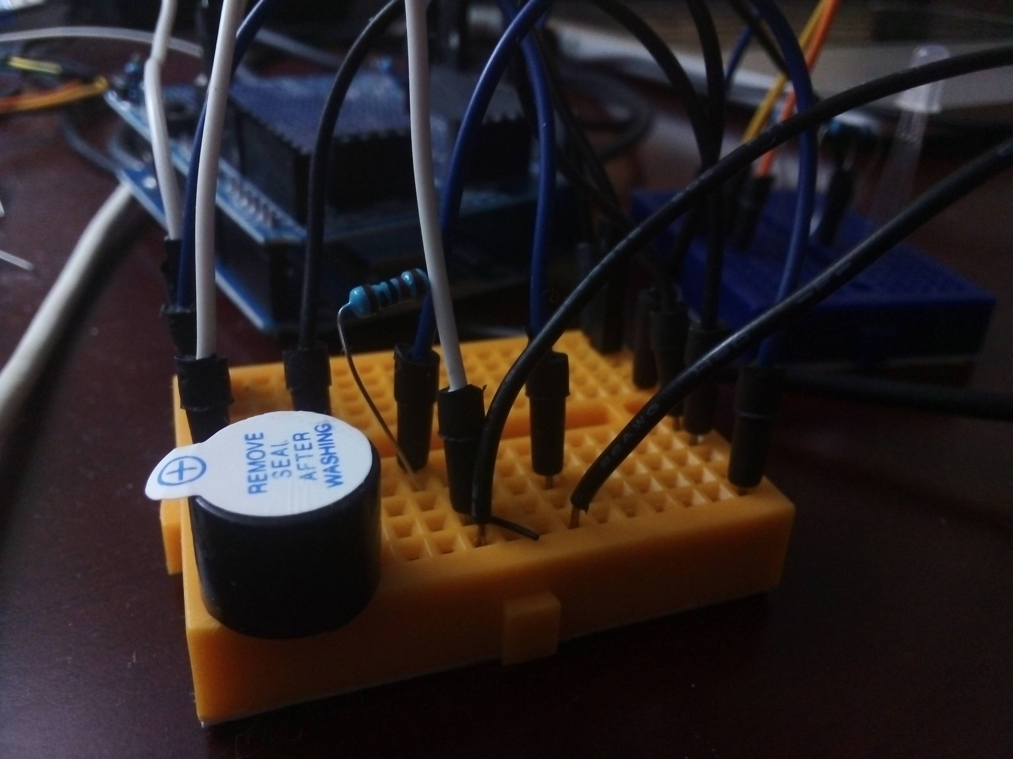
Anyway, everything was working fine until I decided to replace the standard LEDs with an RGB type. Now, whenever the color red (green & blue are fine) blinks, the speaker makes a tiny chirp. I tried disconnecting the power to the LED, but the chirping still occurs.
If I remove the jumper powering the speaker, or just the ground out, the chirping stops.
So my only guess is that the analogWrite signal for red (255,0,0) coming from the D5 pin is somehow bleeding over to the D13 pin that my speaker is on...?
I'm really confused here. I saw someone else had this problem but they just ended up switching to a new speaker.
I think the signal may even have an effect on the PIR sensor...not 100% sure on that though, so ignore it.
I would really like to know if there's a workaround here that doesn't involve me just using a new speaker - I'm a little disappointed that the signal seems to be bleeding into the other pins.
This is my first time using RGB LEDs so forgive me if I'm being dumb.
Here's the RGB code I'm using (just an example, I'm using it as an intermittent flash on my actual project, but same setup):
int redPin= D5;
int greenPin = D4;
int bluePin = D3;
void setup() {
  pinMode(redPin, OUTPUT);
  pinMode(greenPin, OUTPUT);
  pinMode(bluePin, OUTPUT);
}
void loop() {
  redLight();
  delay(1000);
  redFlash();
    greenLight();
  delay(1000);
  greenFlash();
    blueLight();
  delay(1000);
  blueFlash();
    whiteLight();
  delay(1000);
  whiteFlash();
    purpleLight();
  delay(1000);
  purpleFlash();
}
void setColor(int redValue, int greenValue, int blueValue) {
  analogWrite(redPin, redValue);
  analogWrite(greenPin, greenValue);
  analogWrite(bluePin, blueValue);
}
void redLight() {
  setColor(255, 0, 0);
  }
void redFlash() {
  setColor(0,0,0);
  delay(50);
  setColor(255, 0, 0);
  delay(50);
  setColor(0,0,0);
  delay(50);
  setColor(255, 0, 0);
  delay(50);
  setColor(0,0,0);
  delay(50);
  setColor(255, 0, 0);
  delay(50);
  setColor(0,0,0);
  delay(50);
  }

  void greenLight() {
  setColor(0, 255, 0);
  }
void greenFlash() {
  setColor(0,0,0);
  delay(50);
  setColor(0, 255, 0);
  delay(50);
  setColor(0,0,0);
  delay(50);
  setColor(0, 255, 0);
  delay(50);
  setColor(0,0,0);
  delay(50);
  setColor(0, 255, 0);
  delay(50);
  setColor(0,0,0);
  delay(50);
  }

  void blueLight() {
  setColor(0, 0, 255);
  }
void blueFlash() {
  setColor(0,0,0);
  delay(50);
  setColor(0, 0, 255);
  delay(50);
  setColor(0,0,0);
  delay(50);
  setColor(0, 0, 255);
  delay(50);
  setColor(0,0,0);
  delay(50);
  setColor(0, 0, 255);
  delay(50);
  setColor(0,0,0);
  delay(50);
  }

  void whiteLight() {
  setColor(255, 255, 255);
  }
void whiteFlash() {
  setColor(0,0,0);
  delay(50);
  setColor(255, 255, 255);
  delay(50);
  setColor(0,0,0);
  delay(50);
  setColor(255, 255, 255);
  delay(50);
  setColor(0,0,0);
  delay(50);
  setColor(255, 255, 255);
  delay(50);
  setColor(0,0,0);
  delay(50);
  }

  void purpleLight() {
  setColor(170, 0, 255);
  }
void purpleFlash() {
  setColor(0,0,0);
  delay(50);
  setColor(170, 0, 255);
  delay(50);
  setColor(0,0,0);
  delay(50);
  setColor(170, 0, 255);
  delay(50);
  setColor(0,0,0);
  delay(50);
  setColor(170, 0, 255);
  delay(50);
  setColor(0,0,0);
  delay(50);
  }

  void LEDOFF() {setColor(0,0,0);}
Any help here would be great - thank you