I'm making a robot car with a R4 Minima. I'm using 4 dc hobby motors with gearboxes that have a simple plastic wheel attached to each (not Mecanum or Omni). Because I am making a graphing system to direct it, I need it to be precise, not to drift off, and be able to turn 90 degrees while staying at the same point. But I'm not sure what the placing of the wheels would be. I am using a 1-foot by 5 3/4 inch piece of plywood for a chassis, could someone please help?
Thanks!
This DIY robot vehicle site has ideas for getting started. You will need motor driver modules.
Unfortunately, the wheels on a 4WD robot will always skid during turns, so it is impossible to make precise turns without sensors for vehicle orientation and location. Look up "4wd robot skid steering".
Some useful skid steering info in this forum post: 4WD Differential Steering?
Would it help if the wheels were placed at the corners of a square? Maybe then the body could rotate about a vertical axis?
Consider how each motor would have to slip to make that work as intended, and how you would control each motor’s slippage.
Could I do what herbschwarz suggested in the 3rd post? would that work on carpet and tiles?
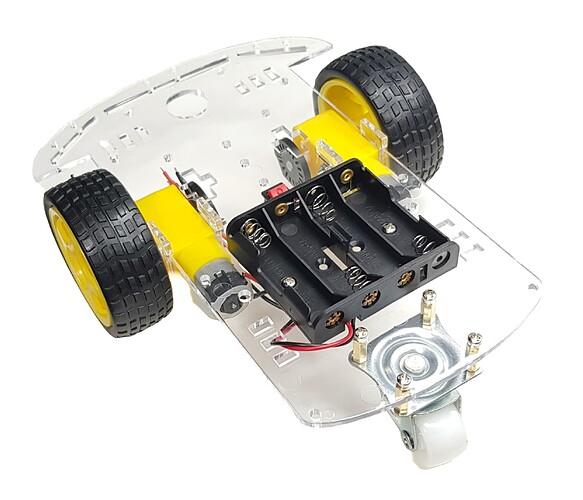
Use two front wheels and a round knob for the back "wheel" (or use a castor wheel). This is how to drive two DC wheel motors to do the eight major movements:
//**************************************************
// L298N MOTOR DIRECTIONS
//**************************************************
//  ENA   ENB   IN1   IN2   IN3   IN4
//  HIGH  HIGH  HIGH  LOW   LOW   HIGH  forward - left forward, right forward
//  HIGH  HIGH  LOW   HIGH  HIGH  LOW   reverse - left reverse, right reverse
//  HIGH  HIGH  LOW   HIGH  LOW   HIGH  face left - left reverse, right forward
//  HIGH  HIGH  HIGH  LOW   HIGH  LOW   face right - left forward, right reverse
//  HIGH  HIGH  LOW   LOW   LOW   HIGH  forward skid left - left stop, right forward
//  HIGH  HIGH  HIGH  LOW   LOW   LOW   forward skid right - left forward, right stop
//  HIGH  HIGH  LOW   HIGH  LOW   LOW   reverse skid left - left reverse, right stop
//  HIGH  HIGH  LOW   LOW   HIGH  LOW   reverse skid right - left stop, right reverse
//  HIGH  HIGH  LOW   LOW   LOW   LOW   stop - all LOW
//  HIGH  HIGH  HIGH  HIGH  HIGH  HIGH  brake - all HIGH - do not use, over current
//  LOW   LOW   N/A   N/A   N/A   N/A   stop - both ENABLE LOW
//
// *** LEFT motor and RIGHT motor are facing opposite directions ***
No, you can't control the slippage to make it move consistently, whether on tile, carpet, grass or mud.
Yes... two motors and a castor. That picture does not have the circuit boards or other devices.
I think I may use a ball caster, but the way i power the wheel is just tank movement? power one side to turn in the opposite direction?
Yes. Just like a "tank" two-stick operation, each wheel has three options: Forward. Idle. Reverse. Using two wheels, you have 2 wheels * 3 Direction Options = 6 drive options. The grid is shown and described in post #6. Then you can have ENA/ENB (enable) connected to a PWM pin which allows variable speed of each of your six drive option.
This topic was automatically closed 180 days after the last reply. New replies are no longer allowed.
