Hello all. I need a little bit of help on my project. I wanted to verify if my wiring diagram and code were right before I started purchasing components. This project is meant to be used with my aerospace senior design project. My team is making a hybrid power rocket motor that runs on Nitrous Oxide. During flight the engine is design to be throttled by limiting the amount of N2O entering the combustion chamber using an electronic proportionality valve.
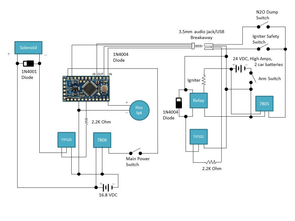
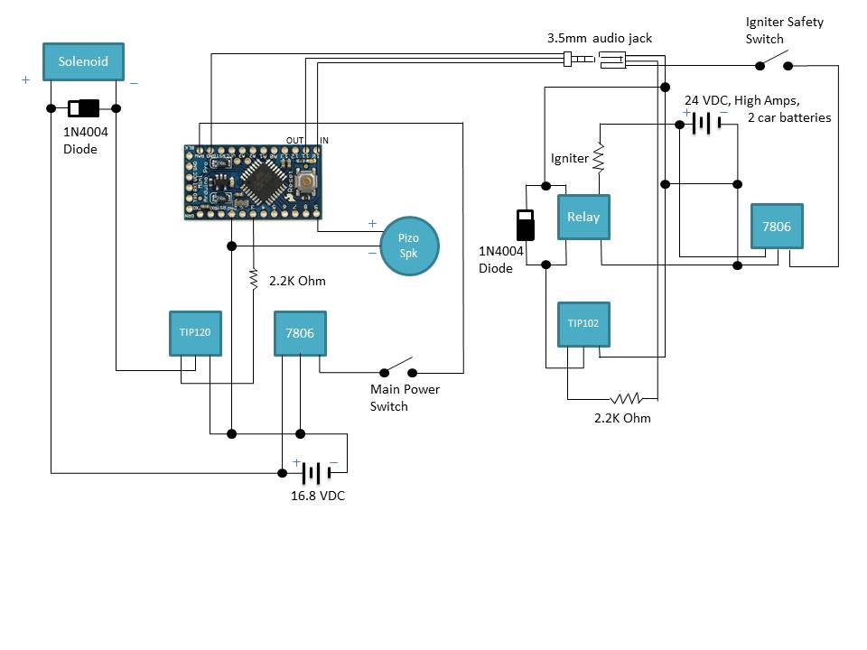
ATTACHED IS THE SCHEMATIC
I'm planning on using the arduino pro mini since I already have this on hand. Basically the 7806 IC is designed to lower the onboard input voltage of ~16VDC from NiMH batteries to an acceptable 6VDC the arduino can handle. The large input voltage is required to operate the electronic proportionality valve. The TIP120 IC is designed to take the PWM low voltage output from pin3 and trigger the internal switch to allow for the 16DC to operate the valve. The pizo speaker is just used to verify audibly that the microcontroller is on since all the electronics will be within the airframe of the rocket. The 3.5mm jack is served to act as a breakaway connection when the rocket lifts off from the launch pad. Everything to the left including the male 3.5mm audio jack will be contained within the rocket. I'm fairly certain I designed everything that goes internal within the rocket correct.
Everything to the right including the female 3.5mm audio jack will be part of the ground support equipment and will stay on the ground. This part of the schematic is where I'm not sure if I completed it correctly. The 24 VDC is provided from 2 12 VDC car batteries to provide enough current to ignite the igniter. The 7806 regulator is designed to take the 24VDC and output a 6VDC to act as the trigger signal. I am worried though if this IC can handle the current draw for a few seconds. I do not know exactly what the max current draw from the igniter will be but it will be certainly high. The TIP102 is designed to take the output voltage from the arduino and trigger the internal switch to trigger the relay to close. I'm not sure if the output voltage from the arduino will be enough to activate the relay. I dont have a specific relay choose yet either, any recommendations would be greatly appreciated.
Operation:
To begin operation, the main switch will be closed to turn on the microcontroller which will then wait for an input trigger (pin 10) from the ignition switch to run the program. Once the launch site is clear and we are ready for lift off, the ignition switch will be closed allowing 6VDC from the 7806 to activate the program run. The arduino will then instantly send a low output voltage on pin 10 to trip the internal switch within the TIP102 which will then activate the relay thereby igniting the igniter. After 1.5 seconds, pin 3 will send a PWM voltage to trip the internal switch within the TIP120 which will then activate and throttle the electronic proportionality valve. By this time the rocket should have lifted off the launch pad and have broken the 3.5mm cable connection. After 2 seconds, the valve will throttle down to 70%. After 10 seconds, the valve will be closed.
Summary of questions:
*Is my wiring diagram correct?
*Is my program correct?
*Can the 7806 IC on the ground support equipment handle short but high current draws?
*Can anyone recommend me any relays that will fit my application? The relay will experience a short term high current draw.
*Will the output from pin 11 be able to provide enough voltage to trigger the relay through the TIP102? I'm pretty sure this one is dependent on the type of relay chosen.
*Inside the void loop, can I have 2 things running at the same time? I want to use the pizeo speaker as an audible method to know that the microcontroller is on since it will be contained withing the rocket body. I need the valve to activate though at anytime when the input trigger is sent.
Reference links that I used to create this diagram:
http://bildr.org/2011/03/high-power-control-with-arduino-and-tip120/
Intelligent Power and Sensing Technologies | onsemi (Page 22, DC applications, did not use capacitors)
Arduino Playground - HomePage
/*
 *  Ignition & Throttle Valve Program
 */

const int triggerPin = 10;         // Trigger is connected to pin 2
int val = LOW;                     // Variable for reading trigger status (float)
const int pizoPin = 9;             // Pizeo Speaker is connected to pin 9
const int valvePin = 3;            // Valve is connected to PWM pin 3
const int ignitorPin = 11;         // Ignitor is connected to pin 11

void setup() {
  pinMode(triggerPin, INPUT);      // Set the trigger pin as input
  pinMode(valvePin, OUTPUT);       // Set the switch pin as input
  pinMode(ignitorPin, OUTPUT);     // Set the switch pin as input
  pinMode(pizoPin, OUTPUT);        // Set the switch pin as input
}


void loop(){

    analogWrite(pizoPin, 255);
    delay(3000);
    analogWrite(pizoPin, 0);
    delay(15000);

  val = digitalRead(triggerPin);   // Read trigger input value and store it in val
  if (val == HIGH) {               // Check if trigger has been tripped
    analogWrite(ignitorPin, 255);  // Ignite ignitor
    delay(1500);		   // Wait for 1.5 seconds
    analogWrite(ignitorPin, 0);    //
    analogWrite(valvePin, 255);    // Open valve 100%
    delay(2000);		   // Wait for 2 seconds
    analogWrite(valvePin, 179);    // Open valve 70%
    delay(10000);	           // Wait for 10 seconds
    analogWrite(valvePin, 0);      // Close valve
	}
}
402 Schematic.pptx (115 KB)