I am new to Arduino so I need some help at a basic level. The project is for a table saw height readout. The blade is attached to an arm so the amount of movement per rotation of the crank is not linear. The arm starts off at -28 degrees down and at full height is + 4 degrees from the plane of the table top. This makes the first rotation of the crank = .21 inches in travel vs the 11th rotation of the crank = .25 inch. There is a total of 13 rotations for about 3 inches of travel. I would like to attach a rotary encoder and digital readout for height in inches. Display of fractions would be great similar to digital calipers. It must remember when turned off or power cut off. I would also like two modes for when a smaller blade is used. The programming will need to be able to handle constantly variable travel rate per rotation. Can someone recommend a rotary encoder, arduino unit and readout and function buttons for this purpose? I plan on mounting the encoder directly to the crank shaft on the back of the saw. It will be on the outside of the cabinet, so not much dust.
Hello oakmot and welcome to the forum.
Have you thought about using a potentiometer instead of an encoder?
A potentiometer always outputs absolute values, unlike an encoder.
Have a nice day and enjoy coding in C++.
While you COULD use a 10 turn pot and gear it, a rotary encoder seems a more appropriate choice.
OK it seems a decent project. I'd suggest you start by getting an encoder something like this
It doesnt have a switch so there are only three connections - ground, A and B
You can follow this tutorial,
but for starters configure the digital pins 2 & 3 as INPUT_PULLUP and just copy the values to leds.
ignore the +5 and swittch connections shown here

What is the resolution needed? The decimal of degrees?
Each turn is about 1/4 of an inch. There will be 13 turns for a total of 3 inches. I want to have a minimum 1/64 of an inch on display. This would be 16 change points per 360 revolution. I would assume that the resolution of the encoder should be much higher to facilitate setting the change point to the correct degree. How high do you think my resolution should be at the encoder?
You will manage using a quite low resolution encoder showing 16 positions per rev. Say 100 or 200 pulses per rev. Look for TTL or Arduino compatible.
from basic metrology concept, use a definition of your encoder > 2* the resolution of your tool.
So 16 points per full rotation give a minimum resolution of 32 points per full rotation on your encoder. Guess it won't be a limitation in the choice of the encoder.
Can you show a drawing of exactly what you will have after you attach the encoder to the shaft? How much vibration will be applied to the encoder? It might bounce from one position to the other with vibration.
The saw is an older very high quality unit that I just replaced all the bushings in. I am still amazed at how quiet and still it is while running. 99% of the time the saw is off while adjusting height. I also am considering using a rubber hose like gas line for the coupling from shaft to encoder. I have to weld a rod to the end of the shaft so it is not going to be at machinist level of true and concentric. I thought of the rubber hose because your question, so thank you for that.
That only connects to the shaft of the encoder. How will you mount the encoder, itself, and avoid vibrations?
You might also consider:
A piece of hose will have a small amount of rotational flex in it so may not give the accuracy wanted.
I just reread your original post. Are you expecting a rotary encoded system to give you the absolute position table height? An encoder can only give direction of movement and the number of steps of the movement.
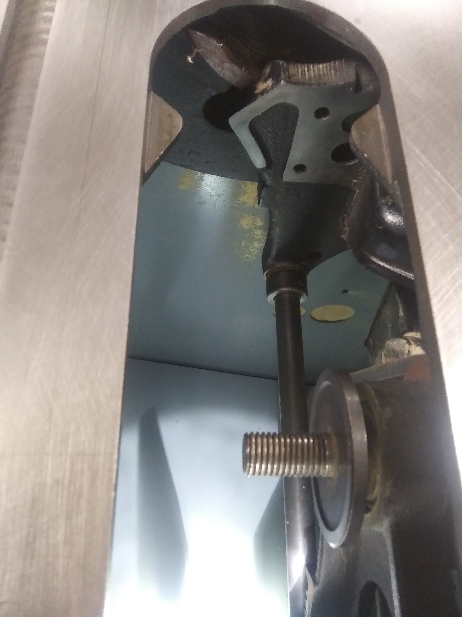
The cast iron frame is next to the back of the cabinet as well as the rear bushing of the height shaft. I will make a bracket to bolt to the cast iron and stick out the back of the cabinet. The cabinet will need a slot cut so that the shaft and the bracket will stick out the back. There is probably enough room to do it in the cabinet, but it is a harsh environment in there.
Yes, absolute position that has memory after turning off and on. I can not calibrate every time I use the saw. It has the added complexity of each turn having a different value on the readout. Turn 1 will move the blade .21 of an inch, but this increases with each turn until it reaches the last few turns that are .25 of an inch per turn. I need to make sure that this level of programming is possible with the hardware I get for this. Can you assign values to positions or is it just a rate of increase per pulse. Or could it be done as the increase is the same, but the number of pulses between changes in the readout makes up for the slower rise of the blade?
I was thinking of getting this one and playing around with it on the bench. Do you think it will do the job? Thanks for the help.
Do you think 128 unique positions will work for your project?
Seems a bit overkill for this, but it supports multi turn according to the website. I hope to give a success update rather than more questions. Thanks to all for the help so far.
Yes, it does, but there is the rub. You and your code has to keep track of the turns discovered when the value of one turn ends and the next begins. Same problem as with the stepper. On power up, you do not know which turn you are on.
Save turns to EEPROM?
How are you going to deal with backlash in the screw and bushing to relate sawblade height accurately to encoder steps? I suppose if the screw is not reversed, when setting the height, then backlash is less of an issue.
You will also need some way to establish an accurate zero point. Of course, everything depends on how accurate you really want the sawblade height to be. I wonder if a distance measuring sensor, like a time-of-flight sensor, (VL530L0X?) over the blade, measuring the height difference between the blade set even with table, and then above it, would work. Accuracy could still be an issue, but at least the backlash issue would not be a problem. Averaging enough values might get you to 1-2 mm accuracy with the sensor over the blade at say 100 mm. The thinness of the blade may be an issue. Some sort of small reflecting plate that could be clipped on the blade could improve precision. Obviously, this would only work on a static blade.
Or maybe even a linear potentiometer with an ADC board, as was kind of suggested previously.