Rotary encoder using pin register interrupts: resets controller

Following program causes controller (Uno) reset whenever the rotary encoder is rotated.

Register manipulation is used to get pins 6 (clock) and pin 7 (data) to invoke an interrupt routine ISR(PCINT0_VECT).

The purpose of the program is to move a stepper inline with rotary encoder revolutions.

What is wrong?

#include <AccelStepper.h>
#define MotorInterfaceType 4  // type 4 = unipolar motor controlled by 4 transistors ie ULN9003
#define MP1  8 // IN1 on the ULN2003
#define MP2  9 // IN2 on the ULN2003
#define MP3  10 // IN3 on the ULN2003
#define MP4  11 // IN4 on the ULN2003
#define ledIR 6 // input for IR led detector
// Rotary Encoder Inputs
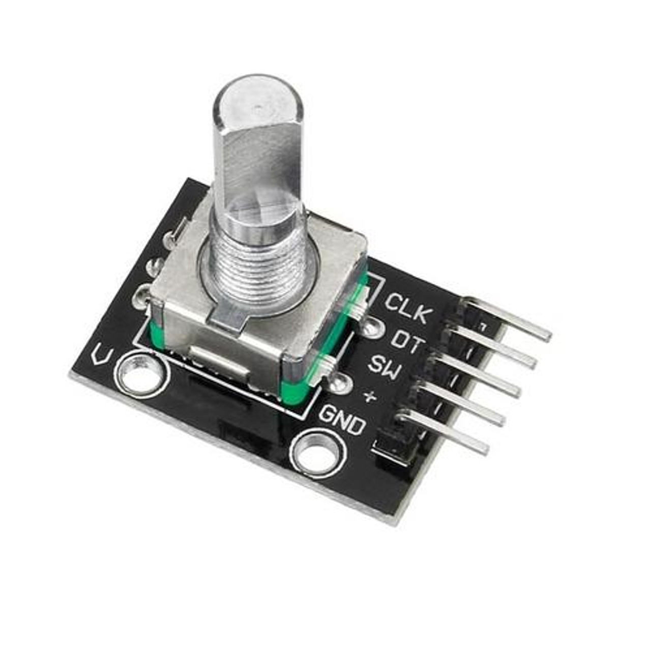
#define clk 6   //Clock pin connected to D6
#define data 7    //Data pin connected to D7
#define btn 5   //Push button pin connected to D5
AccelStepper myStepper(MotorInterfaceType, MP1, MP3, MP2, MP4);  //Define the pin sequence (IN1-IN3-IN2-IN4)
float rcvdSpeed, rcvdAccel;
long int rcvdDistance;
int counter = 0;                    //Use this variable to store "steps"
int previous_counter = 0;           //Use this variable to store previous "steps" value
int currentStateClock;              //Store the status of the clock pin (HIGH or LOW)
int StateData;                      //Store the status of the data pin (HIGH or LOW)
int lastStateClock;                 //Store the PREVIOUS status of the clock pin (HIGH or LOW)
String currentDir = "";             //Use this to print text
unsigned long lastButtonPress = 0;  //Use this to store if the push button was pressed or not
uint16_t aState, aLastState; //GPIO #4-DT on encoder (Output B)

void setup() {
  Serial.begin(9600);
  delay(500);
  Serial.println("DCCpp_turntable_controller_v2");
  // set the maximum speed, acceleration factor,
  // initial speed and the target position
  myStepper.setMaxSpeed(1000.0);
  myStepper.setAcceleration(30.0);
  myStepper.setSpeed(200.0);
  // myStepper.moveTo(2000);
  myStepper.disableOutputs();
  Serial.println(" output disabled ");
  pinMode(clk, INPUT_PULLUP);
  pinMode(data, INPUT_PULLUP);
  aLastState = digitalRead(clk);

  //Here we activate pin change interruptions on pin D8 and D9 with PCINT0 and PCINT1
  PCICR |= (1 << PCIE2);  // set PCICR register bit 2 (PCIE2: PCINT[23:16], 0B00000100
  PCMSK2 |= (1 << PCINT22); // pin 6 PCINT22, 0B01000000
  PCMSK2 |= (1 << PCINT23); // pin 7 PCINT23, 0B10000000

  // Read the initial state of Clock pin (it could be HIGH or LOW)
  lastStateClock = digitalRead(clk);
}

void loop() {
  if (counter != previous_counter)
  {
    Serial.print("Counter: ");
    Serial.println(counter);
  }
  delay(1);
  runStepper(counter);
}

void runStepper(int ctr)
{
  myStepper.enableOutputs(); //enable pins
  myStepper.moveTo(ctr); //-1 is to match the rotation of the encoder with the rotation of the stepper
  while (myStepper.distanceToGo() != 0)
  {
    myStepper.runToNewPosition(ctr);
  }
}

/*In this case, the counter will automatically change its value in the interruption.
  So all we need to do is to print its value in the void loop*/
ISR(PCINT0_vect) {
  cli(); //We pause interrupts happening before we read pin values
  currentStateClock =   (PIND & 0B01000000);       //Check pin D6 state? Clock
  StateData  =   (PIND & 0B10000000);              //Check pin D7 state? Data

  if (currentStateClock != lastStateClock) {
    // If "clock" state is different "data" state, the encoder is rotating clockwise
    if (StateData != currentStateClock) {
      counter  ++;                                // We increment
    }
    //Else, the encoder is rotating counter-clockwise
    else {
      counter --;                                 // We decrement
    }
    lastStateClock = currentStateClock;         // Updates the previous state of the clock with the current state
    sei(); //restart interrupts
  }
}

Hello brice3010

Post a detailed circuit diagram to see how we can help.

Was this code generated by a robot?

No this code was written by me.

I would not even know how a "robot" would write anything of the sort, or anything for that matter.

A schematic: how do i do that for this purpose here?

If it may help:

The rotary encoder is connected as shown in the code:
clock to D6
data to D7
switch to D5

The stepper (ULN9003):
IN1 to D8
IN2 to D9
IN3 to D10
IN4 to D11

Can you give us a link to the rotary encoder that you are using?

How are you powering the Arduino and stepper motor?

If the Arduino Uno is resetting when you rotate the rotary encoder, then I would suspect either a wiring error, or your power supply isn't capable of supplying enough current to be able to drive the stepper motor and Arduino.

Please learn more about interrupts.

Enabling interrupts in an ISR is very bad practice, may cause a stack overflow and consequential reset.

Global variables changed in the ISR should be flagged volatile and deserve atomic access outside the ISR.

You are enabling PCINT2

You are handling PCINT0. When you get a pin change on PCINT22 or PCINT23 you will be jumping to an unhandled interrupt and the Arduino will reset.

Change that line to:
ISR(PCINT2_vect) {

2 Likes

Since you only need one encoder, why not use the Uno pins that support external interrupts (2 & 3)?
There are many interrupt-based encoder libraries available. Have you tried any?

Agree with @gfvalvo: the Arduino encoder library is very reliable.

A schematic: how do i do that for this purpose here?

Pencil and paper works very well for communicating circuit diagrams. Post a photo of your artwork.

@JohnLincoln
This is the encoder used.

Ok

I am afraid I do not understand; can you please give an example?

@gfvalvo

For the challenge; I have used the hardware interrupts before, I would like to get this method to learn about using register manipulation.

Lol, "artwork" attached: (I did not know it was that simple :wink:)

That works, thanks johnwasser.

Now the stepper moves forward (counter++ works). Each encoder step makes the stepper move one step.
But reversing (counter-- ) does not yet work.. ?

EDIT: when moving forward all 4 stepper motor phases are active.
When moving reverse direction then only 3 phases work: IN1 never is active.

In the isr the code does show incrementing counter values (rotary encoder moved CW), and the stepper moves CCW, but when reversing the rotary encoder rotation (CCW) then the counter does not decrease value:

ISR(PCINT2_vect) {
  //cli(); //We pause interrupts happening before we read pin values
  // currentStateClock =   (PINB & B00000010);       //Check pin D9 state? Clock
  currentStateClock =   (PIND & 0B01000000);       //Check pin D6 state? Clock
  // StateData  =   (PINB & 0B00000001);              //Check pin D8 state? Data
  StateData  =   (PIND & 0B10000000);              //Check pin D7 state? Data
  if (currentStateClock != lastStateClock) {
    // If "clock" state is different "data" state, the encoder is rotating clockwise
    if (StateData != currentStateClock) {
      counter  ++;                                // We increment
    }
    //Else, the encoder is rotating counter-clockwise
    else {
      counter --;                                 // We decrement
    }
    lastStateClock = currentStateClock;         // Updates the previous state of the clock with the current state
    // sei(); //restart interrupts
  }
}

This topic was automatically closed 180 days after the last reply. New replies are no longer allowed.