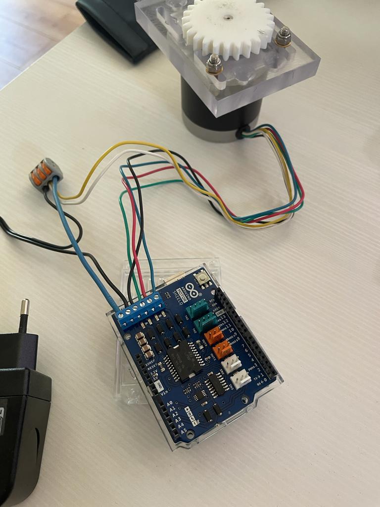
I connected the 4 phase wires to the corresponding letters in the datasheet.
And the 2 coms to the GND of the motor shield.
power supply (+) on VIN (-) on GND with 2 coms
Is there a mistake?
200 step motor (1.8°)
I would like to create a programme that runs the motor
Motor in initial position at 8am [0°].
Then 10° every hour at once
9h[10°]
10h[20°]
11h[30°]
12h[40°]
13h[50°]
14h[60°]
15h[70°]
16h[80°]
17h[90°]
18h[100°]
19h[110°
20h[120°]
9pm back to [0°] to start again the next morning
Waiting 13 hours = 8h next day => restart programme
All this will of course be improved as the sun shines and the programme is implemented, but the aim is to understand how the programme works.
For my tests, we can change the hours to minutes to see how well it works.
Can anyone help me?
I've only found this link and it's causing the cards to heat up and the engine not to run at all.
I don't know
The aim is to start the programme one day at the time I want.
Doesn't the button on the arduino motor system start the programme automatically?
I start the 1st day at 8 o'clock and then it's on an automatic 24-hour cycle that never stops.
From 9pm in the evening to 8am in the morning, I make it wait for 13 hours and the programme starts again in a loop.
Is this possible?
well, it is possible. but i am not sure if this motor shield is suitable for unipolar connection. probably you can leave this two middle point wires unplugged and using motor as bipolar. then test example sketch for stepper. then if it work adapting sketch to your purpose.
but it does mention stepsPerRevolution, 8, 9, 10, 11
But with Shield Moteur
• Broche n°3 en sortie Digitale PWM
• Broche n°11 en sortie Digitale PWM
• Broche n°12 en sortie Digitale
• Broche n°13 en sortie Digitale
Does Stepper.h take these new parameters into consideration?
Which stepper motor do you have exactly? The datasheet of your link in #1 contains 3 different steppers. Not all are suitable for your motor shield.
The shield ist for DC motors and voltage controlled bipolar steppers.
N.B. Your shield uses a very old H-Bridge, which produces very much power loss.
A unipolar will work as a bipolar? I don't understand how.
Now my arduino is no longer recognised by USB PC, yesterday it was very hot when I had the 12v power supply plugged in + 5v from the pc.
I think I fried it
OK, this one should work with your shield. But I suppose if you omit the com wires and use it as bipolar motor you may need 24V ( two coils in series ).