for 100% pwm 40,000 RPM is what is expected as per datasheet im getting a sudden spike in between 34K in the above observation but again it starts to vary
is it because of arduino uno? due to noise and all? i've read it can prove to be inaccurate at times?
should i change arduino uno and use something else? But it is possible to get it with uno right?
Try this version with millis timer instead of delay():
const int pwm_pin = 9;
const int tach_pin = 2;
volatile unsigned long pulse_count = 0;
unsigned long pulseCopy,
              timerStart,
              elapsed;
unsigned int rpm, timerEnd = 1000;
const int pulses_per_revolution = 2;
int pwm = 255;

void setup() {
  Serial.begin(9600);
  pinMode(pwm_pin, OUTPUT);
  analogWrite(pwm_pin, 0);
  pinMode(tach_pin, INPUT);
  attachInterrupt(digitalPinToInterrupt(tach_pin), pulseCounter, FALLING);
  analogWrite(pwm_pin, pwm);
}

void loop() {
  elapsed = millis() - timerStart;
  if(elapsed >= timerEnd)
  {
    timerStart += timerEnd;
    noInterrupts();
    pulseCopy = pulse_count;
    pulse_count = 0;
    interrupts();
    rpm = (pulseCopy * 60) / pulses_per_revolution;

    Serial.print("PWM is: ");
    Serial.print(map(pwm, 0, 255, 0, 100));
    Serial.print("%, RPM: ");
    Serial.print(rpm);
    Serial.println(" rpm");
  }
}

void pulseCounter() {
  pulse_count++;
}i tried that and with that i get this:

its shown 40k in datasheet so with its tolerance it could be in this range right?
so is it working fine?
const int pwm_pin = 9;
const int tach_pin = 2;
volatile unsigned long pulse_count = 0;
unsigned long pulseCopy, timerStart, elapsed;
unsigned int rpm, timerEnd = 1000;
const int pulses_per_revolution = 2;
int pwm = 0;

void setup() {
  Serial.begin(9600);
  pinMode(pwm_pin, OUTPUT);
  analogWrite(pwm_pin, pwm);
  pinMode(tach_pin, INPUT);
  attachInterrupt(digitalPinToInterrupt(tach_pin), pulseCounter, FALLING);
}

void loop() {
  elapsed = millis() - timerStart;
  if (elapsed >= timerEnd) {
    timerStart += timerEnd;
    noInterrupts();
    pulseCopy = pulse_count;
    pulse_count = 0;
    interrupts();
    rpm = (pulseCopy * 60) / pulses_per_revolution;

    Serial.print("PWM is: ");
    Serial.print(map(pwm, 0, 255, 0, 100));
    Serial.print("%, RPM: ");
    Serial.print(rpm);
    Serial.println(" rpm");

    pwm += 51;
    if (pwm > 255) {
      pwm = 0;
    }
    analogWrite(pwm_pin, pwm);
  }
}

void pulseCounter() {
  pulse_count++;
}
i modified your code to find values from duty cycle of 0 to 100% in increments of 20% and its varying a lot from the datasheet
PWM is: 0%, RPM: 14820 rpm
PWM is: 20%, RPM: 21870 rpm
PWM is: 40%, RPM: 21540 rpm
PWM is: 60%, RPM: 21210 rpm
PWM is: 80%, RPM: 28680 rpm
PWM is: 100%, RPM: 11550 rpm
PWM is: 0%, RPM: 14760 rpm
PWM is: 20%, RPM: 20730 rpm
PWM is: 40%, RPM: 20700 rpm
PWM is: 60%, RPM: 25110 rpm
PWM is: 80%, RPM: 40770 rpm
PWM is: 100%, RPM: 22380 rpm
PWM is: 0%, RPM: 14820 rpm
PWM is: 20%, RPM: 38684 rpm
PWM is: 40%, RPM: 44098 rpm
PWM is: 60%, RPM: 31754 rpm
PWM is: 80%, RPM: 0 rpm
PWM is: 100%, RPM: 0 rpm
PWM is: 0%, RPM: 120 rpm
PWM is: 20%, RPM: 3990 rpm
PWM is: 40%, RPM: 54104 rpm
PWM is: 60%, RPM: 21690 rpm
PWM is: 80%, RPM: 28050 rpm
PWM is: 100%, RPM: 45000 rpm
PWM is: 0%, RPM: 15150 rpm
PWM is: 20%, RPM: 24390 rpm
PWM is: 40%, RPM: 25890 rpm
PWM is: 60%, RPM: 30060 rpm
PWM is: 80%, RPM: 34770 rpm
PWM is: 100%, RPM: 28500 rpm
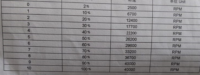
datasheet expected values :
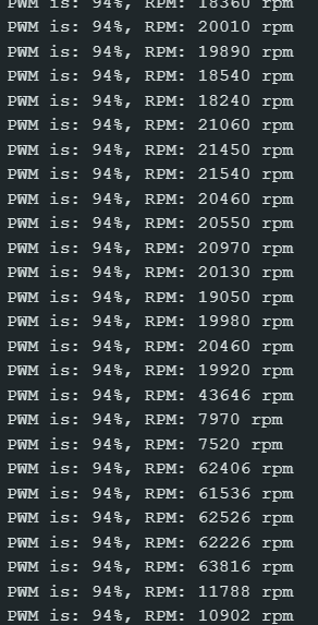
Well, appears better what do you see with PWM 240, 192, 160?
What does the chopped off top line of that picture say?
columns heading are serial number,percentage,rotating speed and unit from the left most column
OK, what speed if PWM wire is disconnected, zero or full speed?
full speed
That makes no sense, post your modified code.
const int pwm_pin = 9;
const int tach_pin = 2;
volatile unsigned long pulse_count = 0;
unsigned long pulseCopy,
              timerStart,
              elapsed;
unsigned int rpm, timerEnd = 1000;
const int pulses_per_revolution = 2;
int pwm = 240;

void setup() {
  Serial.begin(9600);
  pinMode(pwm_pin, OUTPUT);
  analogWrite(pwm_pin, 0);
  pinMode(tach_pin, INPUT);
  attachInterrupt(digitalPinToInterrupt(tach_pin), pulseCounter, FALLING);
  analogWrite(pwm_pin, pwm);
}

void loop() {
  elapsed = millis() - timerStart;
  if(elapsed >= timerEnd)
  {
    timerStart += timerEnd;
    noInterrupts();
    pulseCopy = pulse_count;
    pulse_count = 0;
    interrupts();
    rpm = (pulseCopy * 60) / pulses_per_revolution;

    Serial.print("PWM is: ");
    Serial.print(map(pwm, 0, 255, 0, 100));
    Serial.print("%, RPM: ");
    Serial.print(rpm);
    Serial.println(" rpm");
  }
}

void pulseCounter() {
  pulse_count++;
}
What is the output?

![]()
in datasheet
What RPM reading with PWM disconnected?
const int tach_pin = 2;
volatile unsigned long pulse_count = 0;
unsigned long pulseCopy, timerStart, elapsed;
unsigned int rpm, timerEnd = 1000;
const int pulses_per_revolution = 2;

void setup() {
  Serial.begin(9600);
  pinMode(tach_pin, INPUT);
  attachInterrupt(digitalPinToInterrupt(tach_pin), pulseCounter, FALLING);
}

void loop() {
  elapsed = millis() - timerStart;
  if (elapsed >= timerEnd) {
    timerStart += timerEnd;
    noInterrupts();
    pulseCopy = pulse_count;
    pulse_count = 0;
    interrupts();
    rpm = (pulseCopy * 60) / pulses_per_revolution;

    Serial.print("RPM: ");
    Serial.print(rpm);
    Serial.println(" rpm");
  }
}

void pulseCounter() {
  pulse_count++;
}
i used the above code to measure rpm without pwm
output is:

ig its not full speed and is low when pwm pin is disconnected my bad
yet according to datasheet at 2% duty cycle its 2500rpm so like I'm confused
and when i set it to 2% its considerably higher