Well, i'm out of Ideas, don't know what else to try unless it's higher PWM frequency, most computer fans need 25 kHz PWM. Good luck.
That's no good! ![]()
the datasheet says the preferred operating point for the fan is 25khz though
yeah ![]()
Hi, @kaushik0_0
What datasheet?
Please post a link to where you purchased the fan assembly.
Please post a link to specs/data?
I get this from a Google.
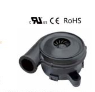
But you show this.
This is not what your circuit diagram in post #7 shows.
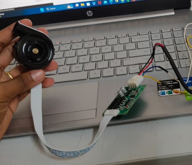
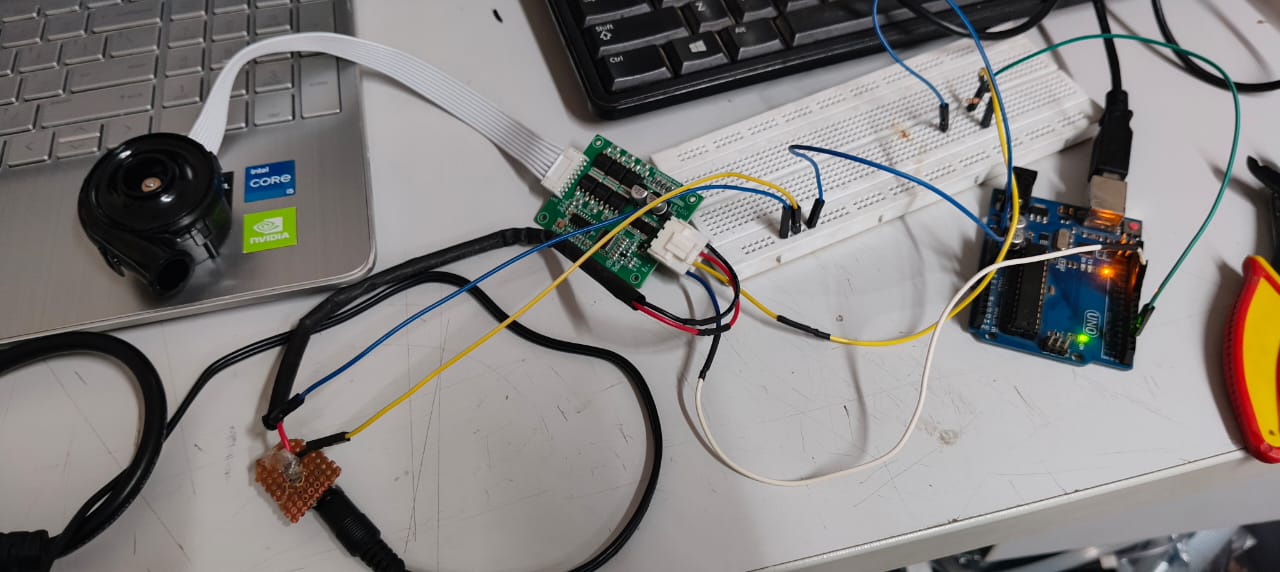
From this image I see two wires from the "speed controller" and the UNO.
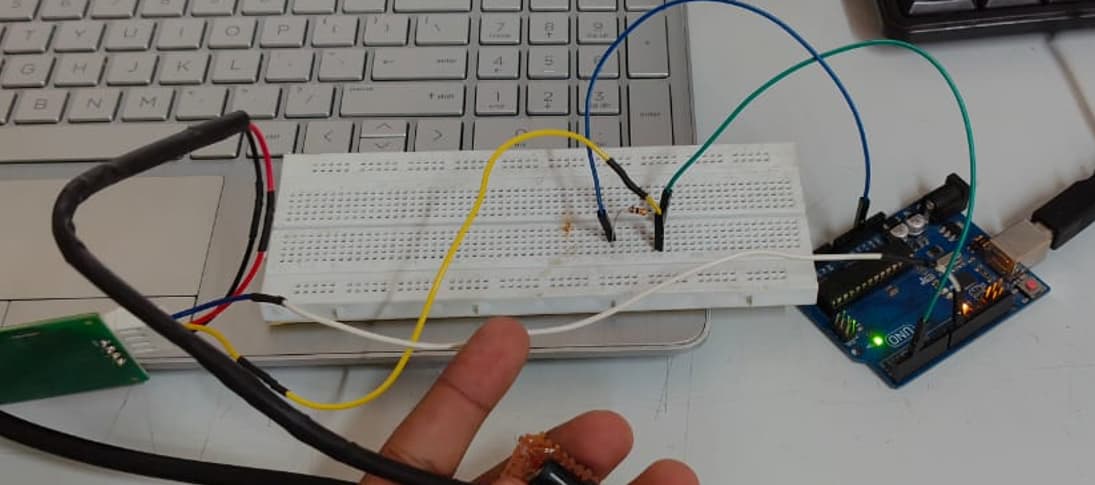
Where is the gnd?
Tom.. ![]()
![]()
![]()
![]()
![]()
![]()
this is the purchase link
also can you be more specific of the ground part i didn't get it should i ground the black wire from blower and also connect it to the 12v supply?
Try this:
Change the 10K resistor to 4.7K or whatever you have that is between 1K and 5K
Use your simple code from post#19 but change the analogWrite to digitalWrite(pwm_pin, HIGH)
Change the pulses_per_revolution to 3.
RPM should be close to 40000.
i disconnected black wire from the connection to 12v and connected it to ground of arduino and connected the 12v the blower wont run
i further made a connection in breadboard connecting it to both ground and the 12v supply it wont run
it only runs when red and black wire both are connected to 12v
am i doing anything wrong?
i used digitalWrite as you mentioned in the following code for both high and low of blower
code:
const int pwm_pin = 9;
const int tach_pin = 2;
volatile unsigned long pulse_count = 0;
unsigned long start_time;
int rpm;
const int pulses_per_revolution = 3;

void setup() {
  pinMode(pwm_pin, OUTPUT);
  digitalWrite(pwm_pin, LOW);

  pinMode(tach_pin, INPUT);
  attachInterrupt(digitalPinToInterrupt(tach_pin), pulseCounter, RISING);

  Serial.begin(9600);
}

void loop() {
  digitalWrite(pwm_pin, HIGH);
  delay(5000);

  pulse_count = 0;
  start_time = millis();
  delay(1000);

  rpm = (pulse_count * 60) / pulses_per_revolution;

  Serial.print("Fan is ON, RPM: ");
  Serial.print(rpm);
  Serial.println(" rpm");

  digitalWrite(pwm_pin, LOW);
  delay(5000);

  pulse_count = 0;
  start_time = millis();
  delay(1000);

  rpm = (pulse_count * 60) / pulses_per_revolution;

  Serial.print("Fan is OFF, RPM: ");
  Serial.print(rpm);
  Serial.println(" rpm");
}

void pulseCounter() {
  pulse_count++;
}
yet output does seem weird
output:
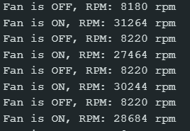
it does not match the datasheet
Well I think you tried everything possible that you could possibly try.
Maybe that driver board for the fan is damage.
yeah could be ill try with another board and get back to you thank you
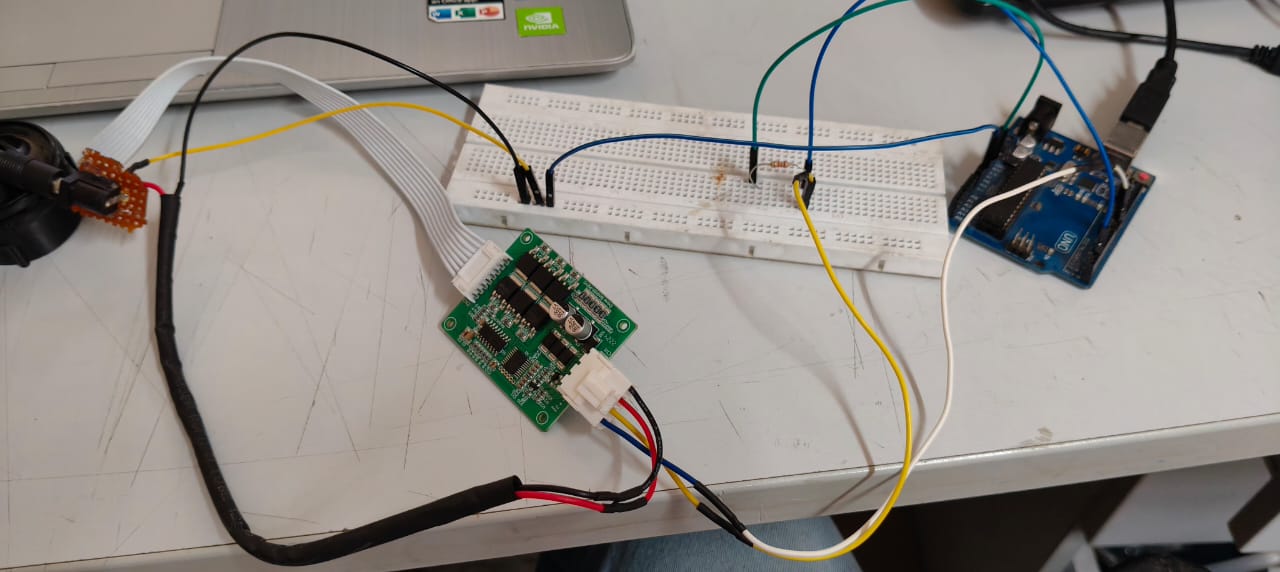
Connect the black wire back to where you disconnected it.
Place a wire from that black wire to the UNO gnd, so the gnd of the motor controller and its power supply and the UNO are all connected together.
Please a link to this data sheet you keep referring to.
Thanks for the Alibaba link,
Tom... ![]()
![]()
![]()
![]()
"DC Brushless Blower".
No wonder the Arduino PWM doesn't work right.
Would have been nice to know that fact 50 replies ago.
Looks like I fell into the same trap I warn beginners about:
"ass-uming"!
Oh , I'm sorry im not aware of it
can you give me more info on why Arduino PWM does not work in DC Brushless Blower?
is it because they have internal electronics which expect a stable DC voltage, not rapid on-off PWM signals, causing ineffective speed control without additional conversion or filtering ?
what could i do?
probably use a PWM to DC converter to get clean DC signal?
Please
BA5025H12B-B2102 (1).pdf (2.9 MB)
this is the datasheet
i did this connection but like the rpm reads as 0 when i run the below code

code:
const int tach_pin = 2;
volatile unsigned long pulse_count = 0;
unsigned long pulseCopy, timerStart, elapsed;
unsigned int rpm, timerEnd = 1000;
const int pulses_per_revolution = 2;

void setup() {
  Serial.begin(9600);
  pinMode(tach_pin, INPUT);
  attachInterrupt(digitalPinToInterrupt(tach_pin), pulseCounter, FALLING);
}

void loop() {
  elapsed = millis() - timerStart;
  if (elapsed >= timerEnd) {
    timerStart += timerEnd;
    noInterrupts();
    pulseCopy = pulse_count;
    pulse_count = 0;
    interrupts();
    rpm = (pulseCopy * 60) / pulses_per_revolution;

    Serial.print("RPM: ");
    Serial.print(rpm);
    Serial.println(" rpm");
  }
}

void pulseCounter() {
  pulse_count++;
}
output:

while if i disconnect ground it shows rpm value
● THE FREQUENCY FOR CONTROL SIGNAL OF THE FAN SHALL BE ABLE TO ACCEPT 16K~32 KHZ.
● THE PREFERRED OPERATING POINT FOR THE FAN IS 25K HZ.
Arduino's PWM frequency is 4.88 kHz or 9.76kHz. Could be your problem?
Arduino PWM can be increased to 31kHz but I've forgotten how, sorry.
Search "Arduino PWM 31kHz".
https://forum.arduino.cc/t/31khz-pwm-on-timer2-atmega8/863871
i used timer1 and tried to get it to work
//with 25khz
const int pwm_pin = 9;
const int tach_pin = 2;
volatile unsigned long pulse_count = 0;
unsigned long start_time;
int rpm;
const int pulses_per_revolution = 2; // Adjust based on your fan's PPR
void setup() {
Serial.begin(9600);
// Timer1 configuration for ~25 kHz PWM on pin 9
pinMode(pwm_pin, OUTPUT);
TCCR1A = 0; // Clear Timer1 control registers
TCCR1B = 0;
TCNT1 = 0; // Clear Timer1 counter register
TCCR1A = _BV(COM1A1) | _BV(WGM11); // Fast PWM mode, non-inverting
TCCR1B = _BV(WGM13) | _BV(WGM12) | _BV(CS10); // No prescaler, Fast PWM mode
ICR1 = 640; // Top value for ~25 kHz PWM frequency (16 MHz / (640 + 1) ≈ 25 kHz)
OCR1A = 0; // Initial PWM duty cycle
pinMode(tach_pin, INPUT);
attachInterrupt(digitalPinToInterrupt(tach_pin), pulseCounter, RISING); // Interrupt on pin 2 for tachometer signal
}
void loop() {
for (int pwm = 0; pwm <= ICR1; pwm += (ICR1 / 5)) { // Increment PWM in steps of 20%
OCR1A = pwm; // Set PWM duty cycle
delay(1000); // Wait for 5 seconds at each PWM level
start_time = millis();
pulse_count = 0;
delay(1000); // Measure pulses for 1 second
rpm = (pulse_count * 60) / pulses_per_revolution;
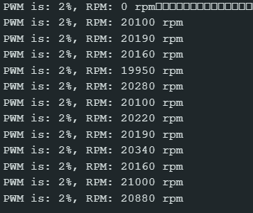
Serial.print("PWM = ");
Serial.print(map(pwm, 0, ICR1, 0, 100)); // Map PWM value to percentage
Serial.print("%, RPM: ");
Serial.print(rpm);
Serial.println(" rpm");
}
}
void pulseCounter() {
pulse_count++; // Increment pulse count on each tachometer pulse
}
yet output isn't matching
