Hi there,
I'm a n00b as you'd put it and out of my depth here. Looking for some guidance please.
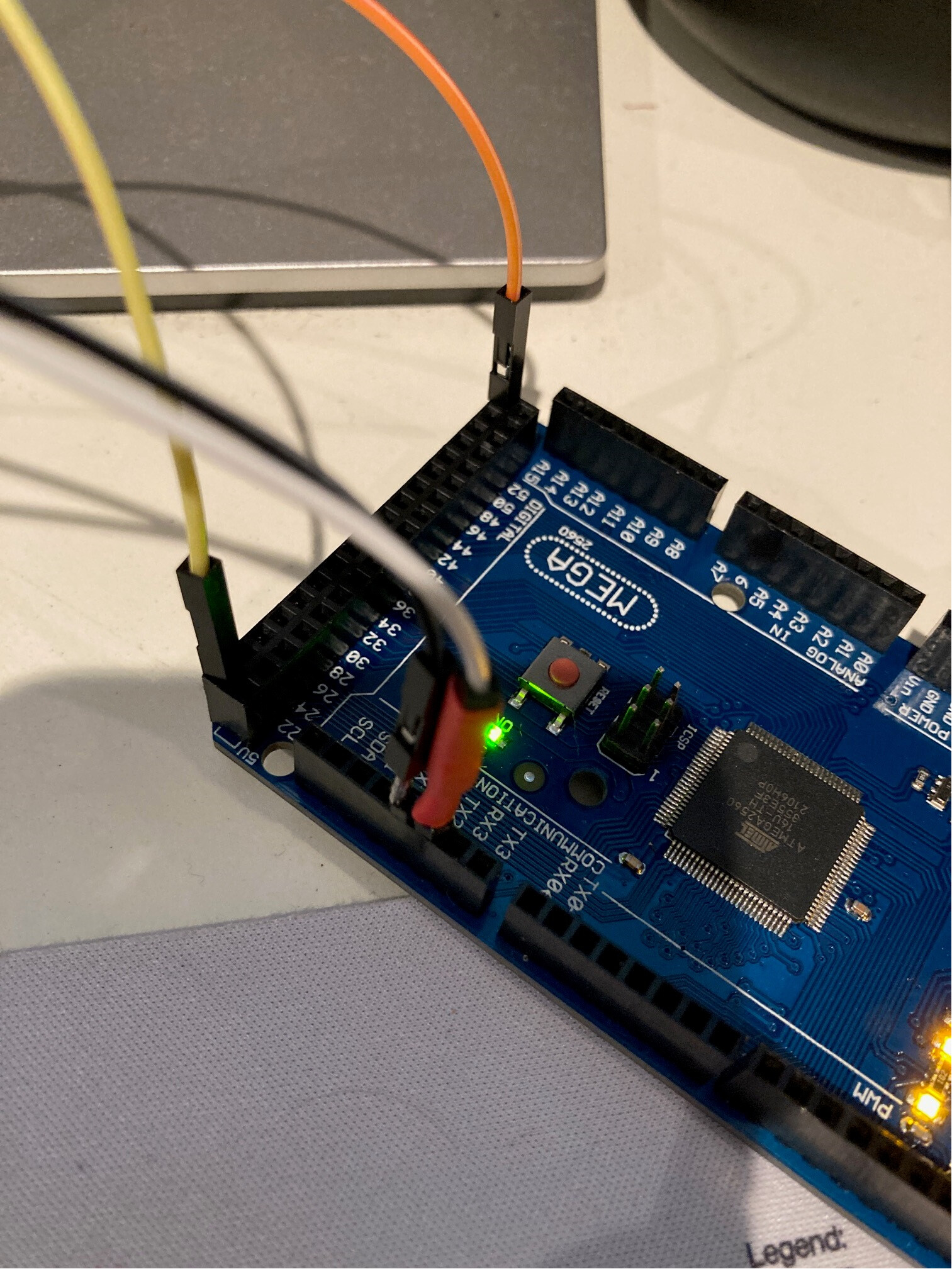
I am trying to interface a TM-8818 device to Mega 2560.
I have run all manner of code from simple to advanced, partly my own work and partly ChatGPT to assist.
I have the device connected to 5v, ground, TX2/RX2.
I wait to see 10h from the device then send 20h to accept the next transmission where i expect to see 08h but never see it. I do some some bytes come through but the results are all over the place, no consistency and I cannot decode it into anything that makes sense.
I am using an adapter (2 actually) JY-R2T V1.4 and HW-044:
Arduino Compatible RS-232 to TTL UART Converter Module | Jaycar Electronics
RS232 to Serial Converter | Core Electronics Australia (core-electronics.com.au)
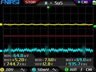
When I check the volts (DC) on the output of the device (which is a 2.5mm stereo plug) I see:
4.2v between the middle band and the ground.
0.8v between the tip and the ground.
The base band is ground.
The 4.2v drops to 4.0v and keeps going between the 2 values in a steady fashion when the probe is in use during a measurement activity.
The 0.8v seems to drop to 0.1v then doesn't do much after that.
When the code is running, and the TX/RX is one way I get back:
14:24:51.826 -> Received data from Serial2 - Byte 1: 0 (Decimal: 0)
14:24:51.924 -> Received data from Serial2 - Byte 2: 0 (Decimal: 0)
14:24:52.023 -> Received data from Serial2 - Byte 3: 0 (Decimal: 0)
14:24:52.153 -> Received data from Serial2 - Byte 4: 0 (Decimal: 0)
14:24:52.252 -> Received data from Serial2 - Byte 5: 0 (Decimal: 0)
14:24:52.350 -> Received data from Serial2 - Byte 6: 0 (Decimal: 0)
14:24:52.481 -> Received data from Serial2 - Byte 7: 0 (Decimal: 0)
14:24:52.579 -> Received data from Serial2 - Byte 8: 0 (Decimal: 0)
14:24:52.710 -> Received complete data from Serial2:
14:24:52.776 -> Byte 1: 0 (Decimal: 0)
14:24:52.808 -> Byte 2: 0 (Decimal: 0)
14:24:52.874 -> Byte 3: 0 (Decimal: 0)
14:24:52.940 -> Byte 4: 0 (Decimal: 0)
14:24:52.973 -> Byte 5: 0 (Decimal: 0)
14:24:53.038 -> Byte 6: 0 (Decimal: 0)
14:24:53.071 -> Byte 7: 0 (Decimal: 0)
14:24:53.136 -> Byte 8: 0 (Decimal: 0)
14:24:53.169 -> Invalid product code received.
When I swap the RX/TX I get:
14:24:56.250 -> Received data from Serial2 - Byte 2: 0 (Decimal: 0)
14:24:56.348 -> Received data from Serial2 - Byte 3: 20 (Decimal: 32)
14:24:56.479 -> Received data from Serial2 - Byte 4: 0 (Decimal: 0)
14:24:56.577 -> Received data from Serial2 - Byte 5: 20 (Decimal: 32)
14:24:56.708 -> Received data from Serial2 - Byte 6: 0 (Decimal: 0)
14:24:56.807 -> Received data from Serial2 - Byte 7: 20 (Decimal: 32)
14:24:56.938 -> Received data from Serial2 - Byte 8: 0 (Decimal: 0)
14:24:57.036 -> Received complete data from Serial2:
14:24:57.102 -> Byte 1: FE (Decimal: 254)
14:24:57.167 -> Byte 2: 0 (Decimal: 0)
14:24:57.232 -> Byte 3: 20 (Decimal: 32)
14:24:57.265 -> Byte 4: 0 (Decimal: 0)
14:24:57.331 -> Byte 5: 20 (Decimal: 32)
14:24:57.396 -> Byte 6: 0 (Decimal: 0)
14:24:57.429 -> Byte 7: 20 (Decimal: 32)
14:24:57.494 -> Byte 8: 0 (Decimal: 0)
14:24:57.527 -> Invalid product code received.
14:24:57.593 -> Received data from Serial2 - Byte 1: 20 (Decimal: 32)
14:24:57.724 -> Received data from Serial2 - Byte 2: 0 (Decimal: 0)
14:24:57.822 -> Received data from Serial2 - Byte 3: 20 (Decimal: 32)
14:24:57.953 -> Received data from Serial2 - Byte 4: FE (Decimal: 254)
14:24:58.051 -> Received data from Serial2 - Byte 5: 20 (Decimal: 32)
14:24:58.182 -> Received data from Serial2 - Byte 6: FE (Decimal: 254)
14:24:58.281 -> Received data from Serial2 - Byte 7: 0 (Decimal: 0)
14:24:58.412 -> Received data from Serial2 - Byte 8: 20 (Decimal: 32)
14:24:58.510 -> Received complete data from Serial2:
14:24:58.609 -> Byte 1: 20 (Decimal: 32)
14:24:58.641 -> Byte 2: 0 (Decimal: 0)
14:24:58.707 -> Byte 3: 20 (Decimal: 32)
14:24:58.740 -> Byte 4: FE (Decimal: 254)
14:24:58.805 -> Byte 5: 20 (Decimal: 32)
14:24:58.871 -> Byte 6: FE (Decimal: 254)
14:24:58.903 -> Byte 7: 0 (Decimal: 0)
14:24:58.969 -> Byte 8: 20 (Decimal: 32)
14:24:59.035 -> Invalid product code received.
I believe this is more correct but still I don't know how to decode the feedback or whether it's even giving me back any real data at all.
The RX and TX lights never blink on the RS232-TTL Adapter.
The TX light on the Mega 2560 is lit constantly, no blinking.
The RX light on the Mega 2560 remains unlit the whole time.
This is the documentation I was provided with, but I don't know its accuracy. On one hand it was given to me as a Bluetooth data protocol but on the other it was claimed to be for RS232.
Data flow:
- Send 10H ;always begin with 10H
reply: not agree to receive : FFH
agree to receive: 20H - Send 08H and start to accumulate the sum ; will send 8 bytes continuously as below
- Then send the 8-bytes Da
1st byte is the product code,
e.g. 06H (MtypeCode), meaning Ultrasonic Thickness Meter
2nd byte is function code, see the table below. (DtypeCode),
E.g. 11 H meaning Cast Iron,its unit is mm
3rd to 7th byte (from high to low),digit 0-9h, meaning 0-9
0Ah, do not display
8th byte is dot position
0 mean integer (no dot)
1 means 1 bit dot (xx.x)
2 means 2 bit dot (x.xx)
3 means 3 bit dot (x.xxx)
4 means 4 bit dot (x.xxxx)
5 means Negative, 1 bit dot (-xx.x)
6 means Negative,2 bit dot (-x.xx) - Send the accumulative sum
MTypeCode MTypeName DTypeCode DTypeName Unit
06 Ultrasonic Thickness Gauge 11 Cast Iron mm
06 Ultrasonic Thickness Gauge 12 Steel mm
06 Ultrasonic Thickness Gauge 13 Aluminium mm
06 Ultrasonic Thickness Gauge 14 Red Copper mm
06 Ultrasonic Thickness Gauge 15 Brass mm
06 Ultrasonic Thickness Gauge 16 Zinc mm
06 Ultrasonic Thickness Gauge 17 Quartz Glass mm
06 Ultrasonic Thickness Gauge 18 Polyethylene mm
06 Ultrasonic Thickness Gauge 19 PVC mm
06 Ultrasonic Thickness Gauge 20 Gray Cast Iron mm
06 Ultrasonic Thickness Gauge 21 Nodular Cast Iron mm
06 Ultrasonic Thickness Gauge 22 Measured by Velocity mm
06 Ultrasonic Thickness Gauge 23 Gold mm
06 Ultrasonic Thickness Gauge 24 Silver mm
06 Ultrasonic Thickness Gauge 25 Platinum mm
06 Ultrasonic Thickness Gauge 26 Palladium mm
06 Ultrasonic Thickness Gauge 31 Cast Iron inch
06 Ultrasonic Thickness Gauge 32 Steel inch
06 Ultrasonic Thickness Gauge 33 Aluminium inch
06 Ultrasonic Thickness Gauge 34 Red Copper inch
06 Ultrasonic Thickness Gauge 35 Brass inch
06 Ultrasonic Thickness Gauge 36 Zinc inch
06 Ultrasonic Thickness Gauge 37 Quartz Glass inch
06 Ultrasonic Thickness Gauge 38 Polyethylene inch
06 Ultrasonic Thickness Gauge 39 PVC inch
06 Ultrasonic Thickness Gauge 40 Gray Cast Iron inch
06 Ultrasonic Thickness Gauge 41 Nodular Cast Iron inch
06 Ultrasonic Thickness Gauge 42 Measured by Velocity inch
06 Ultrasonic Thickness Gauge 43 Gold Inch
06 Ultrasonic Thickness Gauge 44 Siver Inch
06 Ultrasonic Thickness Gauge 45 Platinum Inch
06 Ultrasonic Thickness Gauge 46 Palladium Inch
These devices (TM-8818) are very common low-cost item sold under many different brands and model numbers; I imagine there's a very simple way to collect the data.
Now on the below code, my basic flow should be to wait for 10h from the device, respond with 20h to accept the data flow... expect 08h to signify the start of data transmission, followed by:
06H, 32, 0, 0, 0, 4, 5, 1, ??
Expecting measurement of 4.5mm from the above, I think?
That's what the screen on the device is showing
My current code, courtesy of ChatGPT (please go easy on me, I started with very basic code but got nowhere):
Also, I tried connecting the adapter via FTDI usb plug straight to my pc and use terminal programs and also putty but I got nowhere..
I hope I have provided enough details.
Thanks in advance for any support.
// Global variables
const int waitTime = 10000; // 10 seconds
const int baudRate = 4800; // Baud rate for communication
byte incomingByte;
byte commandBuffer[8]; // Buffer for 8 bytes of data
int byteIndex = 0; // Index for storing data in commandBuffer

// Setup function
void setup() {
  // Initialize all serial interfaces
  Serial.begin(baudRate);
  Serial1.begin(baudRate);
  Serial2.begin(baudRate);
  Serial3.begin(baudRate);
  Serial.println("Setup complete. Starting communication...");

  // Start communication with the device
  startCommunication();
}

void loop() {
  // Interrogate each serial interface
  Serial.println("Interrogating devices...");
  readSerialData(Serial, "Serial");
  readSerialData(Serial1, "Serial1");
  readSerialData(Serial2, "Serial2");
  readSerialData(Serial3, "Serial3");

  // Wait for 10 seconds before repeating
  delay(waitTime);
}

void startCommunication() {
  Serial.println("Sending 20H...");
  Serial2.write(0x20); // Send command to agree to receive data

  // Wait for the device to send 08H
  Serial.println("Waiting for 08H response...");
  while (Serial2.available() == 0) {
    // Wait for a response
  }

  byte response = readResponse(Serial2);
  Serial.print("Response received: ");
  Serial.println(response, HEX);

  if (response == 0x08) {
    Serial.println("Received 08H. Expecting 8 bytes of data...");
    for (int i = 0; i < 8; i++) {
      readSerialData(Serial2, "Serial2");
    }
  } else {
    Serial.println("Did not receive expected 08H.");
  }
}

byte readResponse(Stream& serial) {
  if (serial.available()) {
    return serial.read();
  }
  return 0; // No response
}

void readSerialData(Stream& serial, const char* serialName) {
  while (serial.available()) {
    incomingByte = serial.read();

    Serial.print("Received data from ");
    Serial.print(serialName);
    Serial.print(" - Byte ");
    Serial.print(byteIndex + 1);
    Serial.print(": ");
    Serial.print(incomingByte, HEX);
    Serial.print(" (Decimal: ");
    Serial.print(incomingByte, DEC);
    Serial.println(")");

    commandBuffer[byteIndex++] = incomingByte;

    if (byteIndex >= 8) {
      Serial.print("Received complete data from ");
      Serial.print(serialName);
      Serial.println(":");

      for (int i = 0; i < 8; i++) {
        Serial.print("Byte ");
        Serial.print(i + 1);
        Serial.print(": ");
        Serial.print(commandBuffer[i], HEX);
        Serial.print(" (Decimal: ");
        Serial.print(commandBuffer[i], DEC);
        Serial.println(")");
      }

      // Check for valid product code
      if (commandBuffer[0] == 0x06) {
        // Extract the function code
        byte functionCode = commandBuffer[1];
        Serial.print("Function Code: ");
        Serial.println(functionCode, HEX);

        // Build the measurement from bytes 3 to 7
        int measurement = 0;
        for (int i = 0; i < 5; i++) {
          measurement = (measurement * 10) + (commandBuffer[i + 2] & 0x0F);
        }

        // Check dot position from byte 8
        int dotPosition = commandBuffer[7];
        if (dotPosition > 0 && dotPosition < 5) {
          float decimalFactor = pow(10, -dotPosition);
          measurement *= decimalFactor;
        } else if (dotPosition >= 5 && dotPosition < 7) {
          measurement = -measurement; // Apply negative
          float decimalFactor = pow(10, -(dotPosition - 4));
          measurement *= decimalFactor;
        }

        Serial.print("Measurement: ");
        Serial.println(measurement);
      } else {
        Serial.println("Invalid product code received.");
      }

      byteIndex = 0; // Reset for next reception
    }

    serial.write(0x20); // Respond with 20H
  }

  if (byteIndex == 0) {
    Serial.print("No data available on ");
    Serial.println(serialName);
  }
}

edit: sorry I forgot to add, probably very important.
This is the monitor feedback I get on the Arduino when the device is off and unplugged !!!!
Clearly creating its own data.
14:49:31.898 -> Received data from Serial2 - Byte 1: 20 (Decimal: 32)
14:49:31.996 -> Received data from Serial2 - Byte 2: 0 (Decimal: 0)
14:49:32.127 -> Received data from Serial2 - Byte 3: 0 (Decimal: 0)
14:49:32.226 -> Received data from Serial2 - Byte 4: 20 (Decimal: 32)
14:49:32.357 -> Received data from Serial2 - Byte 5: 20 (Decimal: 32)
14:49:32.455 -> Received data from Serial2 - Byte 6: 0 (Decimal: 0)
14:49:32.554 -> Received data from Serial2 - Byte 7: 20 (Decimal: 32)
14:49:32.685 -> Received data from Serial2 - Byte 8: 0 (Decimal: 0)
14:49:32.782 -> Received complete data from Serial2:
14:49:32.881 -> Byte 1: 20 (Decimal: 32)
14:49:32.914 -> Byte 2: 0 (Decimal: 0)
14:49:32.979 -> Byte 3: 0 (Decimal: 0)
14:49:33.012 -> Byte 4: 20 (Decimal: 32)
14:49:33.078 -> Byte 5: 20 (Decimal: 32)
14:49:33.143 -> Byte 6: 0 (Decimal: 0)
14:49:33.176 -> Byte 7: 20 (Decimal: 32)
14:49:33.242 -> Byte 8: 0 (Decimal: 0)
14:49:33.274 -> Invalid product code received.