It has a 120ohm resistor at data lines however it is not connected (R0 is absent).
As far as I can understand it is something related to impedance matching.
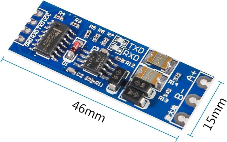
The question is: should I leave it like this (open) or short if all I want is to connect 2 identical modules to make a communication line between two UARTs? The picture below is what I bought, R13 seemed to be R0 from the pic above
And a little question about the ground: should the third output pin (next to A+ and B-) be connected to the ground or it should be connected to the 3rd pin of another transiever? I read about 2 and 3 wires on RS485 connections but since my electronics knowledge is very limited i was not able to understand it.
Some schematic use just two wires and have that third line locally grounded (connected to power supply ground). Some web pages insist that 3rd line must connect two RS485 transievers (so it is a third signal line?).
Or should be that pin connected to common ground? Both of my rs485 transievers are powered from the same power source.
I'd opt for this if you can spare the additional conductor:
No, it's a ground reference. I think it's a good idea to use it to reference both modules to the same GND level because there's no isolation of the actual signal lines.
Ground reference is not actually required, the polarity of the A & B lines define logic HIGH or LOW. Typically GND is used to shield the lines (as with DMX) and in that case may as well be only connected at one end. If GND is connected at both ends, an electrical mishap on one end can cause damage on the other end. If that can not happen there is no risk involved in connecting GND at both ends.
as long as a 2 way transmission between 2 devices, than yes a 120R terminator at both ends. In case of a one way transmission only at the receiving end. With multiple devices use a maximum of 2x 120R terminators at the end of the rail. (or just the one if it is a one way transmission)
Why do you need these RS485 modules at all? Are the UARTs that far apart? And be aware that your RS485 module is a half duplex design. You cannot send/receive at the same time. Your software has to control the direction of transmission.
Yes these ESP32 UART's are 22m away from each other. One of them is underwater (sea) and another is on the island. They are connected via shielded twisted pair (ethernet CAT5 cable).
This is ok, it is a Request->Response logic. Host's uart will transmit a command and then read the reply. Slave device is quiet until it receives a command from a host
That's not true, there we go again. GND reference is not required, the A & B lines reference each other. Their polarity determines the logic HIGH or LOW
Erroneous information that the OP found on the internet.
The connections contradict the RS485 specification.
That is why you and the OP are confused about grounds.
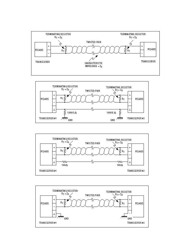
And this is from the Maxim datasheet, None of the images show a shared GND anywhere. To be fair i was under the same impression as you were until it was pointed out to me that common GND was not part of the MAX485 connections. (or DMX specification where i use them most)
None of the images shows any connections to Vcc or Gnd. These are only informal images regarding the data connections.
Both ends are not galvanically isolated. The common mode voltage range of the differential receiver is limited, so driver and receiver need a common reference. And that is Gnd.
Module is clearly doing the 'turn around' internally, if you actually look at the schematic. No access to DE/RE is provided. While this suffices 'most of the time', these modules can sometimes be a problem. The OP will have to determine correct functionality.
For a two device connection, jumper in the 120 ohm resistors at both ends.
OP has stated both ends are powered from same source, so we have a common reference. The discussion of whether there should be such a connection in all RS485 installations is moot in this instance, though I continue to agree with @jim-p, and I have suffered the consequences of not making this connection more than once. In particular, PC->instrument installations where the original PC has a frame ground, connected to a similarly grounded instrument, but the replacement portable computer has a two-prong (no GND) power supply with 'Class 2' intrinsically safe ratings, has been the source of multiple problems in industrial environments.
@Deva_Rishi In my limited experience, most of the time when people make the statements you are making, a thorough investigation will reveal hidden, parasitic, or inadvertent ground connections that are 'doing the job'. If you have instances where this has been determined to NOT be the case, I'm interested. But you must be able to demonstrate >10 Megohm isolation between the power grounds of the two ends of the connection, or I'm not convinced.