RS485 master slave communication failure

Hi,

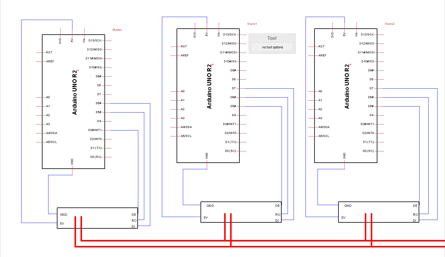
I have a system containing one master arduino (UNO), and 11 slaves (arduino UNO).
I'm using the RS485 module for communication, see
https://arduino-info.wikispaces.com/RS485-Modules
, with the MAX 485 chip.
I'm also using the library by Nick Gammon, see Gammon Forum : Electronics : Microprocessors : RS485 communications
to make sure no corrupt messages are read (interpreted as ok messages).

The communication works fine for longer periods, but from time to time, the connection fails (and is never recovered).
Sometimes the master loses the connection to all the slaves, and sometimes the communication works for e.g slave 1 and 2, and fails for slave 3-11. Resetting the slaves "solves" the problem.

What may be the issue here ?
Is it a buffer somewhere in the SoftwareSerial library that is never emptied, or is it a hardware issue ?
Or something else ?

Master code:

#include <SPI.h>
#include <avr/wdt.h>
#include <SoftwareSerial.h>
#include <RS485_protocol.h>

#define SSerialRX        5  //Serial Receive pin
#define SSerialTX        6  //Serial Transmit pin

#define SSerialTxControl 3   //RS485 Direction control


#ifndef sbi
  #define sbi(sfr, bit) (_SFR_BYTE(sfr) |= _BV(bit))
#endif

SoftwareSerial RS485Serial(SSerialRX, SSerialTX); // RX, TX

const boolean debug = false;

void fWrite(const byte message)
{
  RS485Serial.write(message);
}

int fAvailable()
{
  return RS485Serial.available();
}

int fRead()
{
  return RS485Serial.read();
}

byte slaveAddresses[11] = {
  11, 12, 13, 14, 15, 16, 17, 18, 19, 20, 21
};
byte slaveValues[11] = {
  0, 0, 0, 0, 0, 0, 0, 0, 0, 0, 0
};
byte slaveIdCounter = 0;


unsigned long statusTimer = 0;
unsigned long statusDelay = 2000;

void setup() {
  Serial.begin(9600);
  sbi(UCSR0B, TXEN0);
  pinMode(SSerialTxControl, OUTPUT);
  digitalWrite(SSerialTxControl, LOW);  // Init Transceiver
  RS485Serial.begin(4800);   // set the data rate

  statusTimer = millis() + statusDelay;
}

void loop() {
    if (slaveIdCounter >= sizeof(slaveValues)) {
      slaveIdCounter = 0;
    }
    readSlaveStatus(slaveIdCounter);
}

void readSlaveStatus(byte slaveId) {

  if((unsigned long)(millis() - statusTimer) >= statusDelay) {
    // Write to RS485 bus, using address for given slave
    byte address = slaveAddresses[slaveId];
    byte message[2] = {address, 9};
    Serial.println("sending to");
    Serial.println(address);
    UDR0 = 1;
    digitalWrite(SSerialTxControl, HIGH);  // Enable RS485 Transmit
    sendMsg(fWrite, message, sizeof(message));
    flushTransmissionBuffer();
    digitalWrite(SSerialTxControl, LOW);  // Disable RS485 Transmit

    // Wait for answer on RS485 bus, save answer to slaveValues array
    byte received[3] = {0, 0, 0};
    unsigned long ms = millis();
    while (!recvMsg(fAvailable, fRead, received, sizeof(received)))
    {
        if (millis() > ms + 3000) {
          Serial.println("not receiverd any message");
          break;
      }
    }
    if (received[1] == 9 && received[0] == address)
    {
      Serial.println("received message");
      Serial.println(received[2]);
      slaveValues[slaveId] = received[2];
    }
    statusTimer = millis();
    slaveIdCounter += 1;
  }
}

void flushTransmissionBuffer() {
  while (!(UCSR0A & (1 << UDRE0))) // Wait for empty transmit buffer
  {
    UCSR0A |= 1 << TXC0; // mark transmission not complete
  }
  while (!(UCSR0A & ( 1 << TXC0))); // Wait for the transmission to complete
}

slave code:

/*-----( Import needed libraries )-----*/
#include <RS485_protocol.h>
#include <SoftwareSerial.h>


/*-----( Declare Constants and Pin Numbers )-----*/
#define SSerialRX        6   //Serial Receive pin
#define SSerialTX        7  //Serial Transmit pin

#define SSerialTxControl 5   //RS485 Direction control

/*-----( Declare objects )-----*/
SoftwareSerial RS485Serial(SSerialRX, SSerialTX); // RX, TX

int slave_id = 11;

const int numberOfPins = 6;
const int pinArray[numberOfPins] = {13, 12, 11, 10, 9, 8};

static int counter = 0;

template<class T> inline Print &operator <<(Print &obj, T arg) {
  obj.print(arg);
  return obj;
}

void fWrite(const byte command)
{
  RS485Serial.write(command);
}

int fRead()
{
  return RS485Serial.read();
}

int fAvailable()
{
  return RS485Serial.available();
}


void setup()  
{
  Serial.begin(9600);
  for (int i = 0; i < numberOfPins; ++i) {
    pinMode(pinArray[i], INPUT);
    digitalWrite(pinArray[i], HIGH);
  }
  
  pinMode(SSerialTxControl, OUTPUT);
  digitalWrite(SSerialTxControl, LOW);  // Init Transceiver
  RS485Serial.begin(4800);   // set the data rate

}//--(end setup )---


void loop()   /****** LOOP: RUNS CONSTANTLY ******/
{
    byte received[3];
    if(recvMsg(fAvailable, fRead, received, sizeof(received)))
    {
      Serial << "Received = " << received[0] << " slave_id = " << slave_id << "n";
      if(received[0] == slave_id)
      {
          byte command = received[1];
          byte message[] = {
            slave_id,
            command,
            0
          };
          if(command == 9)  // send connection status
          {
            message[2] = getStatus();
            Serial << "Sending = " << message[2] << "n";
            delay(10);
            digitalWrite(SSerialTxControl, HIGH);
            sendMsg(fWrite, message, sizeof(message));
            while(!(UCSR0A & (1 << UDRE0)))
              UCSR0A |= 1 << TXC0;
            while(!(UCSR0A & ( 1 << TXC0)));
            digitalWrite(SSerialTxControl, LOW);
          }
      }
    }
}


byte getStatus()
{
  byte result = 0;
  for(int i = 0; i < numberOfPins; ++i)
  {
    if(digitalRead(pinArray[i]) == LOW)  
    {
        result = result + 1;
    }
  }
  return result;
}

I suggest you also post the schematic diagram as well.

The diagram is attached.

The lower rectangles describes the MAX 485 chip, for more info, see : https://arduino-info.wikispaces.com/SoftwareSerialRS485Example

bump

I have used RS485 links extensively but always used hardware serial port as opposed to the SoftwareSerial. For this reason i use arduinos than have extra hardware serial port for example Arduino Leonardo, Mega or micro. I use Serial1 for the RS485 while the original Serial port is used for the terminal connection with the PC.

Guffen:
bump

What are you trying to do here?

         if(command == 9)  // send connection status
          {
            message[2] = getStatus();
            Serial << "Sending = " << message[2] << "n";
            delay(10);
            digitalWrite(SSerialTxControl, HIGH);
            sendMsg(fWrite, message, sizeof(message));
            while(!(UCSR0A & (1 << UDRE0)))
              UCSR0A |= 1 << TXC0;
            while(!(UCSR0A & ( 1 << TXC0)));
            digitalWrite(SSerialTxControl, LOW);

As I interpret it, you send a message out the HardwareSerial port, delay a little bit. The put your RS485 into transmit, send a message
Then do some home brew Hardware Transmit complete horse play. You attempt to overwrite the TX complete IRQ (trying to keep HardwareSerial from actually processing the interrupt?) then wait for a TX Complete IRQ to be triggered?
Then go back into RS485 Receive mode.

Are you just trying to do a Serial.flush() for the HardwareSerial, or did you think you are 'flushing' SoftwareSerial?

Is your schematic accurate? Are all of the UNO's wired the same or is the first one different? I would put a pullup on RO, the RO output is triStated when you go into TX Mode. Unless SoftwareSerial enables the INPUT_PULLUP on D6, that input would be floating, possibly generating random values while in tx mode.

Chuck.

What are you trying to do here?

First I read the status
delay for a little bit
send the message using Nick Gammon's lib (Gammon Forum : Electronics : Microprocessors : RS485 communications)
Then (from the same web-page): The first loop waits for the hardware chip's buffer to empty, at the same time setting the "transmission not complete" flag. The second loop waits for the final byte to be clocked out by the hardware.
Then disable sending messages.

Are all of the UNO's wired the same or is the first one different?

All the slaves are wired the same way, but the master is wired differently (using other pins for communication)

Guffen:
First I read the status
delay for a little bit
send the message using Nick Gammon's lib (Gammon Forum : Electronics : Microprocessors : RS485 communications)
Then (from the same web-page): The first loop waits for the hardware chip's buffer to empty, at the same time setting the "transmission not complete" flag. The second loop waits for the final byte to be clocked out by the hardware.
Then disable sending messages.
All the slaves are wired the same way, but the master is wired differently (using other pins for communication)

Your Schematic and Software have the RS485 circuit wired to pins 5,6,7. This code:

while(!(UCSR0A & (1 << UDRE0)))  UCSR0A |= 1 << TXC0;

while(!(UCSR0A & ( 1 << TXC0)));

is messing with Hardware Serial on PIN 0,1?

It has no relation to SoftwareSerial on pins (5,6) that are connected to the MAX485.

Why are you using the data flow thru the Hardware Serial port to switch half duplex mode of the RS485 circuit?

SoftwareSerial.print() does not return until all of the data has been shifted out. so this code would work with SoftwareSerial:

digitalWrite(7,LOW); // switch MAX485 into TX mode
delayMicroseconds(50);  // just 0.05ms of dead time on bus
SoftwareSerial.print("now is the time for all good men to come to the aid of there fellow country men.");
delayMicroseconds(50);
digitalWrite(7,HIGH); // back into RX mode

Now, if you are using HardwareSerial (Serial.print()) the code must be a little different, and the MAX485 must be wired to pins (0,1).

digitalWrite(7,LOW);
delayMicroseconds(50);
Serial.print("now is the time for all good men to come to the aid of there fellow country men.");
Serial.flush();
delayMicroseconds(50);
digitalWrite(7,HIGH); //

The reason I had to add Serial.flush() is that the HardwareSerial object uses a 64byte TX buffer. The Serial.print() just fills the buffer and initiates an background interrupt service routine to feed each byte from the buffer to the UART. The Serial.flush() actual waits until all bytes have been queued in the TX buffer are actually sent out the UART before it returns.

Now just to mess with your mind, SoftwareSerial.flush() empties the RECEIVE buffer. Since SoftwareSerial does not use a TRANSMIT buffer at all, there is no value for a function that waits for SoftwareSerial to finish sending data. As soon as the SoftwareSerial.print() returns, the Transmit is done.

Chuck.

Now just to mess with your mind, SoftwareSerial.flush() empties the RECEIVE buffer. Since SoftwareSerial does not use a TRANSMIT buffer at all, there is no value for a function that waits for SoftwareSerial to finish sending data. As soon as the SoftwareSerial.print() returns, the Transmit is done.

Just a question: In case there is nothing connected to the 'SoftwareSerial' pins, and since there is no Transmit buffer, what would happen if the program keeps sending data to the software serial port? Will the system freeze?

No, it would send the data on those Pins, even if nothing is connected to it. On the serial port, it can't recognize if there is a slave connected or not.