RTC clock reseting

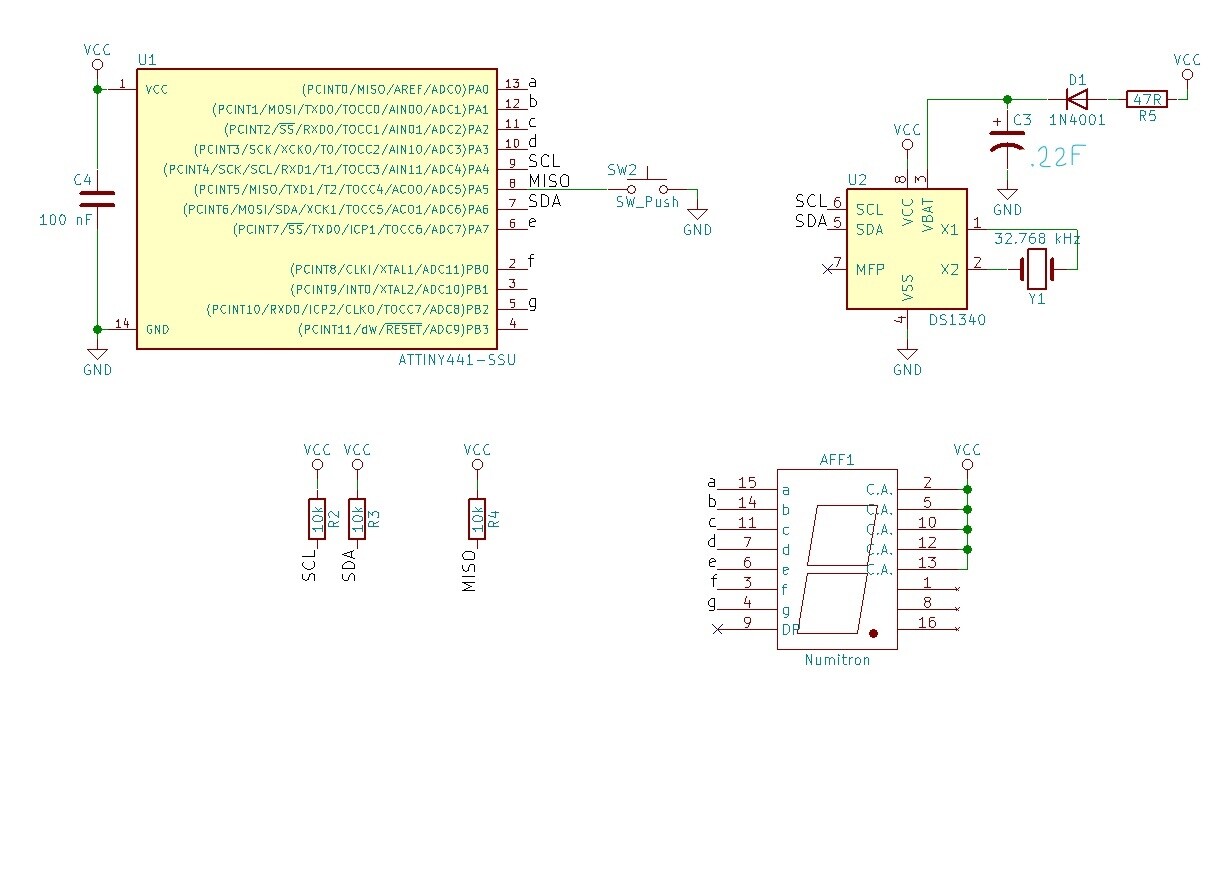
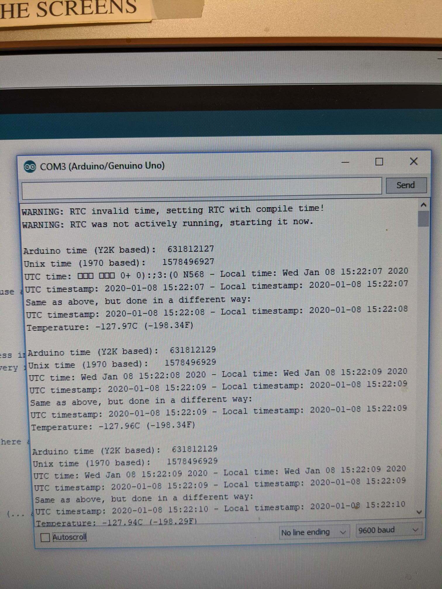
Hello all, first off you must know that I am a complete noob to this stuff. I have been trying to learn a little bit at a time. I am trying to make a single digit seven segment clock and I have the prototype almost working. Today I decided to see if I could switch from USB power( I am using the Arduino Uno as power) to battery power to run my Attiny. When I switched the time reset to 12:00. So I hooked up my Uno to the RTC and set the correct time again. The time was correct again. I proceeded to switch from USB power to battery power. Again it resets to 12:00.

I have done this about 10 times now with the same results. I am using a supercap for RTC backup power and it is charged when power is off. I am pretty sure all my wiring is correct. In fact it used to work, I could unplug the UNO over a weekend and come back and plug the Uno back in and the time would show up correct. I am at a loss, I don't know if I did something to the code or if it is the way I am setting the time. Any help would be greatly appreciated.

Here is my sketch

#include <Wire.h>

// I2C address
#define DS1307 B1101000

// pinout for the 7 segment display
// Starts top center, clock-wise, then
// center line, then dot
byte segment[] = {10, 9, 8, 7, 3, 2, 1};

byte second=0, minute=0, hour=0;
const int buttonPin = 0;     // the number of the pushbutton pin
int buttonState = 0;         // variable for reading the pushbutton status
bool showTime = false;

void updatetime();
void printtime();
void print7digit(byte number);
byte DECTOBCD(byte val);
byte BCDTODEC(byte val);
void clearDisplay();
void checkButton();

void setup() {
  byte i;
  Wire.begin();

  for (i=0; i<8; i++) {
    pinMode(segment[i], OUTPUT);
  }
  clearDisplay();
  // initialize the pushbutton pin as an input:
  pinMode(buttonPin, INPUT);
}

void checkButton() {
  // read the state of the pushbutton value:
  buttonState = digitalRead(buttonPin);

  // check if the pushbutton is pressed.
  // if it is, the buttonState is HIGH:
  if (buttonState == HIGH) {
    showTime = true;
  }
}

void loop() {
  checkButton();
  if(showTime) {
    updatetime();
    printtime();
    showTime = false;
  }
}

// Pull current time off the DS1307
void updatetime() {
  Wire.beginTransmission(DS1307);
  Wire.write(0x00);
  Wire.endTransmission();
  Wire.requestFrom(DS1307, 3);
  // Don't actually use seconds value. Feel free to.
  second = BCDTODEC(Wire.read() & 0x7f);
  minute = BCDTODEC(Wire.read());
  hour   = BCDTODEC(Wire.read() & 0x3f); 
}

// Flash each digit of the time in turn on the 7 segment
void printtime() {
  byte j;
  // Convert from 24 hour to 12 hour mode
  // Should be done on the DS1307. I'm sorry.
  byte temphour = hour % 12;
  if (temphour == 0) {
    // Not zero based, not one based, but 12 based.
    temphour = 12;
  }

  int betweenSegmentDelay = 500;
  int clearDelay = 200;

// Hour
  // Only display highest digit if it's nonzero
  if (temphour > 9) {
    print7digit(temphour/10);
    delay(betweenSegmentDelay); // Repeated magic values in my code? Never!
    clearDisplay();
    delay(clearDelay);
  } else {
    print7digit(0);
    delay(betweenSegmentDelay); // Repeated magic values in my code? Never!
    clearDisplay();
    delay(clearDelay);
  }

  print7digit(temphour % 10);
  delay(betweenSegmentDelay);
  clearDisplay();
  delay(clearDelay);
  
// Minute
  print7digit(minute/10);
  delay(betweenSegmentDelay);
  clearDisplay();
  delay(clearDelay);

  print7digit(minute%10);
  delay(betweenSegmentDelay);
  clearDisplay();
  delay(clearDelay);
/*
// Seconds
  print7digit(second/10);
  delay(betweenSegmentDelay);
  clearDisplay();
  delay(clearDelay);

  print7digit(second%10);
  delay(betweenSegmentDelay);
  clearDisplay();
  delay(clearDelay);
*/
  
  delay(2000);
}

// Display a single digit on the 7 segment
void print7digit(byte number) {
  // Bitfield for digits 0-9
  const byte numtable[] = {B01000000,   // Numeral 0.
                     B01111001,   // Numeral 1.
                     B00100100,   // Numeral 2.
                     B00110000,   // Numeral 3.
                     B00011001,   // Numeral 4.
                     B00010010,   // Numeral 5.
                     B00000010,   // Numeral 6.
                     B01111000,   // Numeral 7.
                     B00000000,   // Numeral 8.
                     B00011000    // Numeral 9.
                    };
  byte litpins = numtable[number];
  byte i;
  for (i=0; i<7; i++) {
    digitalWrite(segment[i], (litpins>>i) & 1);
  }
} 

void clearDisplay() {
  int j;
  for (j=0; j<8; j++) {
    digitalWrite(segment[j], HIGH);
  }
}

byte DECTOBCD(byte val) {
  return ((val/10)<<4) + (val%10);
}
byte BCDTODEC(byte val) {
  return (val>>4) * 10 + (val & 0xf);
}

Here is the sketch on how I am setting the time, it uses the Computer time and sets it automatically. there are three files in the sketch in the attachments.

Again I am a NOOB, most of this was pieced together with help from some of my friends and people on the forums. Thanks in advance

RTCtimeSet.ino (9.05 KB)

RTCtimeUtils.cpp (1.99 KB)

RTCtimeUtils.h (188 Bytes)

I am using a supercap for RTC backup power and it is charged when power is off. I am pretty sure all my wiring is correct.

The DS1307 is designed to run on a battery and not a supercap. My guess is a problem in the wiring. Post schematics of your setup!

I am sorry, I should have mentioned that I am using a 1340 RTC. It is not a module, I pieced all the parts together. I was under the impression that the 1307 library would work for the 1340. Here is a schematic of how the RTC is wired up also the the datasheet for the rtc1340. On page 6 of the datasheet Pin number 3 says i can use a supercap as backup. Maybe I misunderstood.

RTC.png

RTC IC.pdf (223 KB)

Post a complete wiring diagram of your RTC connected to the ATtiny! Your tiny is reading only zeros from the RTC, so this might be another problem. Also the supercap is discharged quite quickly if you touch it with your fingers (remember it's only 50mF!)

Sorry another mistake in the rtc. I have a .22Farad cap not 50mF. It is only big enough to store the data for a couple days. I will try to make a sketch

Here is a basic schematic of how I have it hooked up. The only thing that is different about mine is the pin numbers on the Arduino and seven segment display might not correlate exactly. Other than that this is how I have it hooked up.

How do you power that setup?

That is a more complex problem. I do have a single cell lipo charger in the whole circuit and a boost regulator as well. I am not using them at the moment. I am just trying to get the arduino, RTC and display to work with each other right now. At the moment I am using 5v USB power. I set the time yesterday before I left work. When I came in this morning I checked the time and it was right on. At this very moment I checked the time again and it was way off. So I do not know what is going on. It seems to be very erratic. I should also mention that I am prototyping on one of those solder-less breadboards and I know some of the little holes are worn out. But I also have been checking voltages with a meter and everything seems ok.

But you told us that you're changing from the UNO to a battery powered ATtiny. What battery do you use there?

Yes sorry, I have it set up right now with the attiny and usb power. I do have a small single cell lipo and a boost module that runs it as well. So both ways of powering it work except for one thing. Here are the two situations that are happening.

  1. USB power to the attiny and RTC, then I can use the SDA and SCL jumpers and hook them up to the uno and set the time with my time sketch. I can then plug the SDA and SCL jumpers back into the attiny push my button and it will display the time. But if I remove the 5v usb power for even 5 seconds the time will restart at 12:00. This forces me to set the time again with my UNO.

2.Single Cell lipo battery feeds a 5v boost module. The 5v then powers my attiny and RTC, then I can use the SDA and SCL jumpers and hook them up to the uno to set the time with the time sketch. But this time when I switch the jumpers back to the attiny and push my button the time always says 12:00. Also if I remove battery power it restarts at 12:00.

In both these situations as long as the power is connected the RTC seems to be keeping time, except with the battery it never lets me set the time for some reason.

I dont know why the two power sources would make a difference in setting the time.

? Noise on SCL/SDA ?
Do you have the 4K7 pullup resistors on those two lines ?

I have two 10k resistors on those lines. Is 10K enough? Also I have noticed that my Boost module is kind of loud when a load is hooked up to it it squeals a little bit. It could be interference. Is there any way to clean it up?

Here Is the Module I used.

Recommended is 4K7... 10K may be ok, but since you're having issues - I'd go to 4K7

It did not seem to help at all. I wish there was a way I could just test the RTC by itself from my UNO. There probably is but I am not sure how.

It did not seem to help at all. I wish there was a way I could just test the RTC by itself from my UNO.

Have you tried disconnecting the RTC from the UNO and connecting it again afterwards (without connecting it to the Tiny in between)? If the circuit is OK it should keep the time. Otherwise the solution with the supercap doesn't work as expected by you.

I will try with the uno and see what happens

I disconnected everything and hooked my RTC up directly to the Uno. The RTC is getting power from the 5v and GND on the Uno via red and black jumper wires. I performed two separate tests. I used the RTC time set sketch and the Serial monitor to see what was going on.

First test

Arduino USB power disconnected

5 minutes disconnected

Arduino USB power connected

Second test

5v and GND jumper wires disconnected

5 minutes disconnected

5v and GND jumper wires connected

I hope this helps

So the chip doesn't work on your UNO too. There it's simply set to the compile time again if it failed.

Where do you have your supercap circuit from? The datasheet suggests another way to use a supercap...

I am using the circuit I posted on the first page #2 reply. Also the RTC datasheet is in the same post. I thought I placed the supercap according to the datasheet.

In my interpretation of the datasheet (I might be wrong though) the supercap goes directly from Vbackup to GND and is charged by the trickle charger function (so no connection to Vcc).