Hi all.
Totally newbie here (at coding this kind of stuff): Fyi.
I have a project with an old clock that i just got from my father. It requires a special input to run - I hope you can help me here. This is the clock:

The clock is from an old power-plant and needs the following input:
220v (50Hz) for one of the clocks (i got that sorted ![]() ) , and then a 24v pulse each second for the other clock: that pulse need to change polarity, with each pulse:
) , and then a 24v pulse each second for the other clock: that pulse need to change polarity, with each pulse:
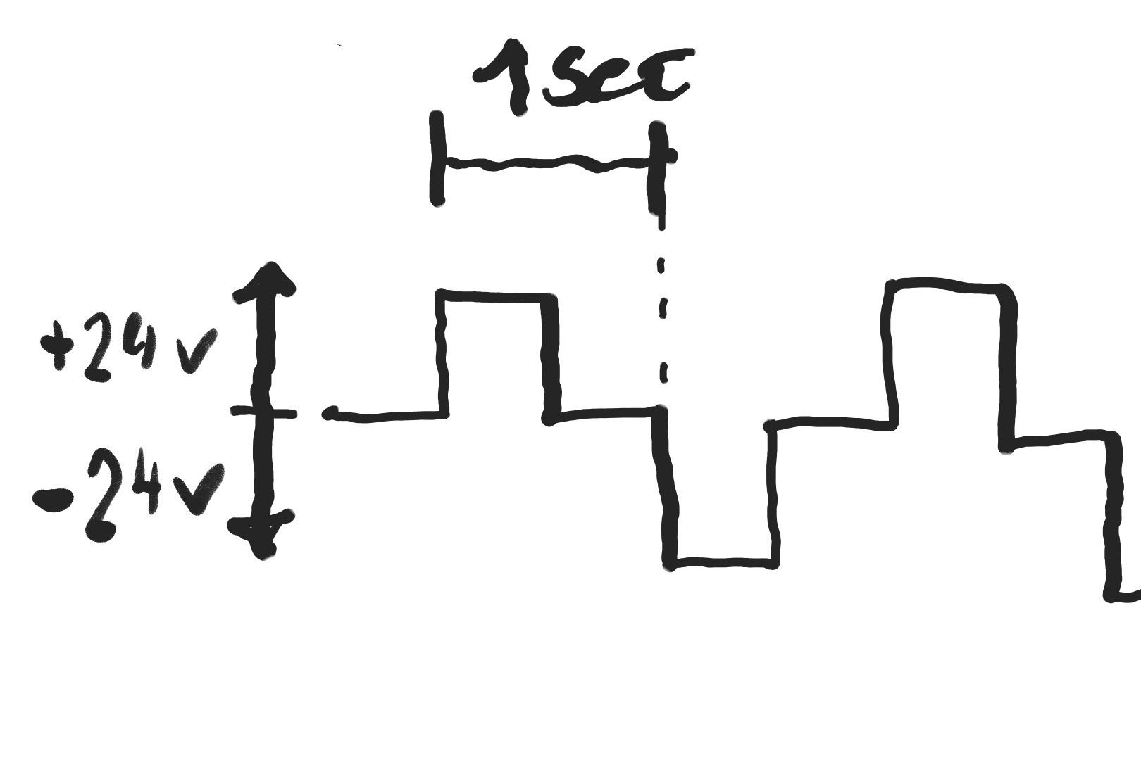
Not sure about the width for each pulse, but lets go with 0,5 seconds.
I have bought following hardware:
ESP32
Motor controller
DC-DC step up converter (to get 24v from a 5v USB source).
My idea is that the motor-controller, will get the input from the ESP32: driving the "motor" forwards and then backwards , according to the above sketch: giving +24v for the first pulse, and then -24v for the second pulse and so on.
I Found this tutorial for driving a motor:
The setup will be similar I guess:

The question is how would I go about coding this into to ESP32? (I have newer coded this kind of thing before).
Also: this is running a clock - is the ESP32 accurate enough for this? (I guess that can be a upgrade for later, if I need an external clock for higher accuracy?).
(I have it successfully connected the ESP32 to my computer, and using the Arduino program - I got it to run a WiFi-scanning program, that is running at the moment).
For the curious about the function of the clock:
The 24v pulses was used to power one part of the clock very accurately (reference time).
The 220v (50Hz) was used on the other clock, to show if the powerplant needed to produce more or less power (the 50Hz will get lower or higher depending on the power available on the grid, thereby changing the speed of that clock).
The operator could then see if they were "behind" or "ahead" in terms of power production.
EDIT: the above explanation is from my father (he was a "low power technician" - he might be wrong or remember incorrectly - He got the clock a LONG time ago ![]()
Kind Regards
Daniel


