Running special clock with motor controller

1.5K sounds OK.

However, there are four motor connections, as the label says 12/24V.

You can connect these in several ways, one of which probably would not require reversing the current flow for alternate steps, just switching between the two 12V coils.

Get googling “ master clock” and “slave clock”.

You have what is called a slave clock . You could do with finding a manual for it, or enthusiasts group. The waveform you show seems a bit odd . I have a Gents setup - the pulse for that is just a single positive going pulse , the timing of it is important, but the pulse length irrelevant .
I’m not saying you are wrong , if you are 100% on that fine .
It’s worth drawing out the circuit diagram of it .

If it’s a power station clock , it’s possible it’s more than one clock - one driven from a master clock , one driven from the generated voltage , so that the voltage frequency can be adjusted

Good :slight_smile:
My father told me to use 24v - that's what they used in the plant (I guess it can run on both 12v and 24v?).
I will try to use the motor controller I have, and see what happens (hopefully not breaking any components on the clock in the process) :slight_smile:

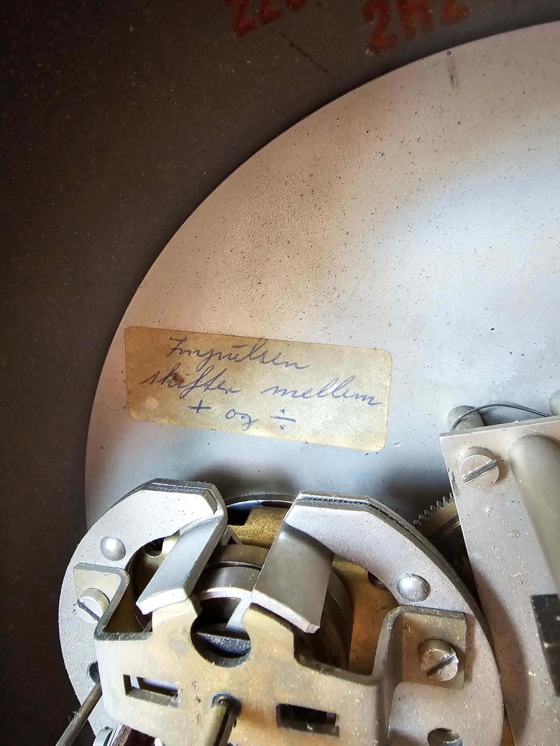
My father was quite precise on the pulses + there is a written note on the clock, that says the same thing (its in Danish, so it does not properly makes sense to you) :slight_smile: It says "the impulse switches between + and -"

And yes there are to clocks in one: one driven by 220v AC (mains) and then this special one that needs the 24v alternating pulses.

Thinking out loud …
That might just mean you connect to those terminals , not the pulse shape .
The more l look at this the more I think it is to do with System time verses real time , or it’s used for synchronising a generator and the outer dial is phase between two sources ???
Interesting device !!

Could do with a model number to google

Heh - not sure - just going from what my father told me :)
I will look, but I have a feeling these were made in VERY small numbers. Perhaps there is no number on it. Will take a look though.
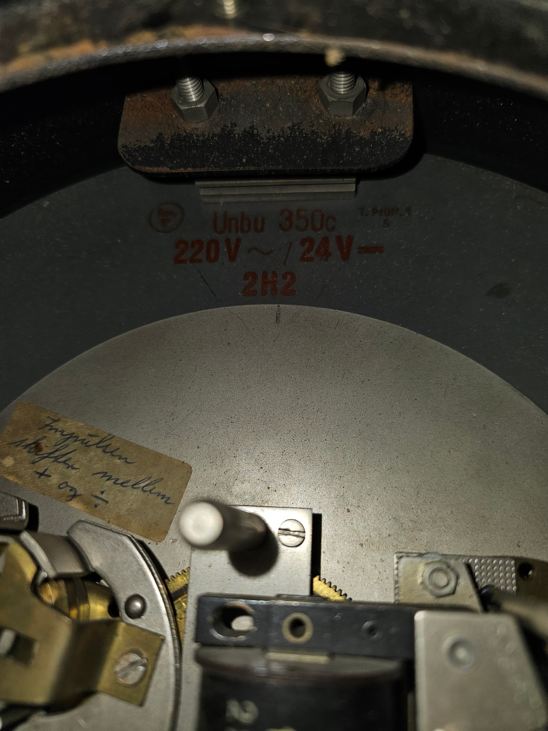
EDIT: found this in the top inside the clock:
"
Unbu 350c
220v ~ / 24V =
2H2
"

Yes, with no internet access, the ESP could not contact the NTP servers. It would lose or gain some seconds per day with only it's own internal clock to rely on.

Also, even if there was wi-fi where the clock will be sited, if you put the ESP inside a metal case, it won't be able to connect. Some ESP32 boards have a connector for an external antenna. If using a board like that, you could connect a small external wi-fi antenna by drilling a hole in the metal case.

But if WiFi is not available, then using an ESP seems like a waste. You could use any small Arduino like a Nano or Pro Micro and save the ESP for another project where it's capabilities would be better used.

The next option would be to use an RTC module. One of the most accurate but inexpensive models is DS3231. This should only lose or gain a few seconds per year. It can be programmed to output a 1s pulse which the Arduino can use to time the 24V pulses to the clock.

Yep , google can’t find anything tho :slightly_frowning_face:

Hi all.

Thank you all for the help - very much appreciated!

I got the clock going :raised_hands:

I used the following code (I haven't looked into the NTP yet, but that will come):

const int in1 = 5;
const int in2 = 4;

void setup() {
  // put your setup code here, to run once:
  pinMode(in1, OUTPUT);
  pinMode(in2, OUTPUT);
}

void loop() {
  // run
  digitalWrite(in1, HIGH);
  digitalWrite(in2, LOW);
  delay(500);

 // pause no pulse
  digitalWrite(in1, LOW);
  digitalWrite(in2, LOW);
  delay(500);

  // change polarity
  digitalWrite(in1, LOW);
  digitalWrite(in2, HIGH);
  delay(500);
  
  // pause no pulse
  digitalWrite(in1, LOW);
  digitalWrite(in2, LOW);
  delay(500);

}

Here is a video of the clock running:

Hi all.

I got the clock back in my home now, after it was with my father during his last time (he died last week, hence the simple code to just make it run, so he could see it in action).

It's been running in my home for about a week now, and the time drift quite a lot (around 30 seconds a week), so now its time to make it more accurate (NTP or External clock).

I'm thinking of using NTP given the accuracy that provides (with an external WiFi antenna, placed outside the metal enclosure). (my current board does not have a connector for an external antenna, but i will get one that does later)

Would i use my current code together with the NTP code, or should the "delay" values be exchanged with something else?

Current code:

const int in1 = 5;
const int in2 = 4;

void setup() {
  // put your setup code here, to run once:
  pinMode(in1, OUTPUT);
  pinMode(in2, OUTPUT);
}

void loop() {
  // run
  digitalWrite(in1, HIGH);
  digitalWrite(in2, LOW);
  delay(500);

 // pause no pulse
  digitalWrite(in1, LOW);
  digitalWrite(in2, LOW);
  delay(500);

  // change polarity
  digitalWrite(in1, LOW);
  digitalWrite(in2, HIGH);
  delay(500);
  
  // pause no pulse
  digitalWrite(in1, LOW);
  digitalWrite(in2, LOW);
  delay(500);

}

Will copy this (more or less) for the NTP: ESP32 NTP Client-Server: Get Date and Time (Arduino IDE) | Random Nerd Tutorials

/*
  Rui Santos
  Complete project details at https://RandomNerdTutorials.com/esp32-date-time-ntp-client-server-arduino/
  
  Permission is hereby granted, free of charge, to any person obtaining a copy
  of this software and associated documentation files.
  
  The above copyright notice and this permission notice shall be included in all
  copies or substantial portions of the Software.
*/

#include <WiFi.h>
#include "time.h"

const char* ssid     = "REPLACE_WITH_YOUR_SSID";
const char* password = "REPLACE_WITH_YOUR_PASSWORD";

const char* ntpServer = "pool.ntp.org";
const long  gmtOffset_sec = 7200;

void setup(){
  Serial.begin(115200);

  // Connect to Wi-Fi
  Serial.print("Connecting to ");
  Serial.println(ssid);
  WiFi.begin(ssid, password);
  while (WiFi.status() != WL_CONNECTED) {
    delay(500);
    Serial.print(".");
  }
  Serial.println("");
  Serial.println("WiFi connected.");
  
  // Init and get the time
  configTime(gmtOffset_sec, ntpServer);
  printLocalTime();

  //disconnect WiFi as it's no longer needed
  WiFi.disconnect(true);
  WiFi.mode(WIFI_OFF);
}

void loop(){
  delay(1000);
  printLocalTime();
}

void printLocalTime(){
  struct tm timeinfo;
  if(!getLocalTime(&timeinfo)){
    Serial.println("Failed to obtain time");
    return;
  }
  Serial.println(&timeinfo, "%A, %B %d %Y %H:%M:%S");
  Serial.print("Day of week: ");
  Serial.println(&timeinfo, "%A");
  Serial.print("Month: ");
  Serial.println(&timeinfo, "%B");
  Serial.print("Day of Month: ");
  Serial.println(&timeinfo, "%d");
  Serial.print("Year: ");
  Serial.println(&timeinfo, "%Y");
  Serial.print("Hour: ");
  Serial.println(&timeinfo, "%H");
  Serial.print("Hour (12 hour format): ");
  Serial.println(&timeinfo, "%I");
  Serial.print("Minute: ");
  Serial.println(&timeinfo, "%M");
  Serial.print("Second: ");
  Serial.println(&timeinfo, "%S");

  Serial.println("Time variables");
  char timeSecond[3];
  strftime(timeSecond,3, "%S", &timeinfo);
  Serial.println(timeSecond);
  Serial.println();
}

Not sure if i need that last part of the code (where it saves the time in variables - i modified the code to seconds). (or any of the above code relating to things other than seconds)

Am I on the right path here and how do i merge the two codes together?
I'm thinking that the NTP should pull the time once every hour (not sure if the board/code does this as standard).

I'm sorry to hear about your father. I'm glad you got the clock working for him to see one last time.

That code will fetch the time from NTP only once after startup, but it won't regularly re-sync itself, so it will drift over time.

I think all you need to do to fix that is remove these lines from setup()

  //disconnect WiFi as it's no longer needed
  WiFi.disconnect(true);
  WiFi.mode(WIFI_OFF);

Or use the code I posted a link to earlier.

/*
  NTP TZ DST - bare minimum
  NetWork Time Protocol - Time Zone - Daylight Saving Time

  Our target for this MINI sketch is:
  - get the SNTP request running
  - set the timezone
  - (implicit) respect daylight saving time
  - how to "read" time to be printed to Serial.Monitor
  
  This example is a stripped down version of the NTP-TZ-DST (v2)
  And works for ESP8266 core 2.7.4 and 3.0.2

  by noiasca
  2020-09-22
*/

#ifndef STASSID
#define STASSID "your-ssid"                            // set your SSID
#define STAPSK  "your-password"                        // set your wifi password
#endif

/* Configuration of NTP */
#define MY_NTP_SERVER "at.pool.ntp.org"           
#define MY_TZ "CET-1CEST,M3.5.0/02,M10.5.0/03"   

/* Necessary Includes */
#include <ESP8266WiFi.h>            // we need wifi to get internet access
#include <time.h>                   // for time() ctime()

/* Globals */
time_t now, lastTime;                         // this are the seconds since Epoch (1970) - UTC
tm tm;                              // the structure tm holds time information in a more convenient way
unsigned long lastTick;

void showTime() {
  localtime_r(&now, &tm);           // update the structure tm with the current time
  Serial.print("year:");
  Serial.print(tm.tm_year + 1900);  // years since 1900
  Serial.print("\tmonth:");
  Serial.print(tm.tm_mon + 1);      // January = 0 (!)
  Serial.print("\tday:");
  Serial.print(tm.tm_mday);         // day of month
  Serial.print("\thour:");
  Serial.print(tm.tm_hour);         // hours since midnight  0-23
  Serial.print("\tmin:");
  Serial.print(tm.tm_min);          // minutes after the hour  0-59
  Serial.print("\tsec:");
  Serial.print(tm.tm_sec);          // seconds after the minute  0-61*
  Serial.print("\twday");
  Serial.print(tm.tm_wday);         // days since Sunday 0-6
  if (tm.tm_isdst == 1)             // Daylight Saving Time flag
    Serial.print("\tDST");
  else
    Serial.print("\tstandard");
  Serial.println();
}

void setup() {
  Serial.begin(115200);
  Serial.println("\nNTP TZ DST - bare minimum");

  configTime(MY_TZ, MY_NTP_SERVER); // --> Here is the IMPORTANT ONE LINER needed in your sketch!

  // start network
  WiFi.persistent(false);
  WiFi.mode(WIFI_STA);
  WiFi.begin(STASSID, STAPSK);
  while (WiFi.status() != WL_CONNECTED) {
    delay(200);
    Serial.print ( "." );
  }
  Serial.println("\nWiFi connected");
  // by default, the NTP will be started after 60 secs
}

void loop() {
  time(&now);                       // read the current time
  if (now != lastTime) {
    if (now & 1 == 0) {
      digitalWrite(in1, HIGH);
      digitalWrite(in2, LOW);
    }
    else {
      digitalWrite(in1, LOW);
      digitalWrite(in2, HIGH);
    }
    lastTick = millis();
    lastTime = now;
    showTime();
  }
  else if (millis() - lastTick > 500) {
    digitalWrite(in1, LOW);
    digitalWrite(in2, LOW);
  }
}

This is how I think it works.
Time uses the freerunning millis() clock until the next NTP update.
Then it checks if millis and epoch are still in sync.
If not, it will correct that millis timer one or more seconds until they are in sync again.
That's not a problem for a digital readout, but it could be for the analogue clock.

See this thread.
Leo..

I think you are more-or-less correct, Leo, but in this project there is no way for the analog clock to be adjusted, that is done by hand. The Arduino code needs only to generate the 1s interval pulses (with alternating +/- voltages) to move the clock hand.

I'm hoping my suggested code will deal with this correctly and not send or miss any pulses when the time is adjusted to sync with NTP. @graaskov84 will need to test that and let us know if there are any problems.

You might find this website helpful.

Right now I'm developing some code to drive a 30s impulse Gent type clock from a DS3231 RTC. Though this needs only unipolar drive it would be trivial to generate bipolar drive. Also you may not need 24V.

The RTC is cheap as chips, has an on-board TCXO, and is accurate to a minute or so per year. No need for NTP etc. I only use the1pps pulse output but it does give you HHMMSS and date if you want it (though needs setting) so would possible to handle DST changes automatically. The real bugbear with these clocks is setting the hands and some buttons and auxiliary code to manage that is worthwhile.

Hi @PaulRB

Thank you. Glad I got it running :slight_smile:

I tried using your code after adding this:

const int in1 = 5;
const int in2 = 4;

The code now looks like this (i also changed it to WiFi.h in the code for the ESP32):

/*
  NTP TZ DST - bare minimum
  NetWork Time Protocol - Time Zone - Daylight Saving Time

  Our target for this MINI sketch is:
  - get the SNTP request running
  - set the timezone
  - (implicit) respect daylight saving time
  - how to "read" time to be printed to Serial.Monitor
  
  This example is a stripped down version of the NTP-TZ-DST (v2)
  And works for ESP8266 core 2.7.4 and 3.0.2

  by noiasca
  2020-09-22
*/

const int in1 = 5;
const int in2 = 4;

#ifndef STASSID
#define STASSID "The Promised LAN"                            // set your SSID
#define STAPSK  "******"                        // set your wifi password
#endif

/* Configuration of NTP */
#define MY_NTP_SERVER "at.pool.ntp.org"            
#define MY_TZ "CET-1CEST,M3.5.0/02,M10.5.0/03"

/* Necessary Includes */
#include <WiFi.h>                   // we need wifi to get internet access
#include <time.h>                   // for time() ctime()

/* Globals */
time_t now, lastTime;               // this are the seconds since Epoch (1970) - UTC
tm tm;                              // the structure tm holds time information in a more convenient way
unsigned long lastTick;

void showTime() {
  localtime_r(&now, &tm);           // update the structure tm with the current time
  Serial.print("year:");
  Serial.print(tm.tm_year + 1900);  // years since 1900
  Serial.print("\tmonth:");
  Serial.print(tm.tm_mon + 1);      // January = 0 (!)
  Serial.print("\tday:");
  Serial.print(tm.tm_mday);         // day of month
  Serial.print("\thour:");
  Serial.print(tm.tm_hour);         // hours since midnight  0-23
  Serial.print("\tmin:");
  Serial.print(tm.tm_min);          // minutes after the hour  0-59
  Serial.print("\tsec:");
  Serial.print(tm.tm_sec);          // seconds after the minute  0-61*
  Serial.print("\twday");
  Serial.print(tm.tm_wday);         // days since Sunday 0-6
  if (tm.tm_isdst == 1)             // Daylight Saving Time flag
    Serial.print("\tDST");
  else
    Serial.print("\tstandard");
  Serial.println();
}

void setup() {
  // put your setup code here, to run once:
  pinMode(in1, OUTPUT);
  pinMode(in2, OUTPUT);
  Serial.begin(115200);
  Serial.println("\nNTP TZ DST - bare minimum");

  configTime(MY_TZ, MY_NTP_SERVER); // --> Here is the IMPORTANT ONE LINER needed in your sketch!

  // start network
  WiFi.persistent(false);
  WiFi.mode(WIFI_STA);
  WiFi.begin(STASSID, STAPSK);
  while (WiFi.status() != WL_CONNECTED) {
    delay(200);
    Serial.print ( "." );
  }
  Serial.println("\nWiFi connected");
  // by default, the NTP will be started after 60 secs
}

void loop() {
  time(&now);                       // read the current time
  if (now != lastTime) {
    if (now & 1 == 0) {
      digitalWrite(in1, HIGH);
      digitalWrite(in2, LOW);
    }
    else {
      digitalWrite(in1, LOW);
      digitalWrite(in2, HIGH);
    }
    lastTick = millis();
    lastTime = now;
    showTime();
  }
  else if (millis() - lastTick > 500) {
    digitalWrite(in1, LOW);
    digitalWrite(in2, LOW);
  }
}

It gives an error though when i verify the code:

C:\Users\graas\OneDrive\Clock\NTP_CLOCK\NTP_CLOCK.ino: In function 'void setup()':
C:\Users\graas\OneDrive\Clock\NTP_CLOCK\NTP_CLOCK.ino:28:15: error: invalid conversion from 'const char*' to 'long int' [-fpermissive]
 #define MY_TZ "CET-1CEST,M3.5.0/02,M10.5.0/03"
               ^~~~~~~~~~~~~~~~~~~~~~~~~~~~~~~~
C:\Users\graas\OneDrive\Clock\NTP_CLOCK\NTP_CLOCK.ino:69:14: note: in expansion of macro 'MY_TZ'
   configTime(MY_TZ, MY_NTP_SERVER); // --> Here is the IMPORTANT ONE LINER needed in your sketch!
              ^~~~~
C:\Users\graas\OneDrive\Clock\NTP_CLOCK\NTP_CLOCK.ino:27:23: error: invalid conversion from 'const char*' to 'int' [-fpermissive]
 #define MY_NTP_SERVER "at.pool.ntp.org"
                       ^~~~~~~~~~~~~~~~~
C:\Users\graas\OneDrive\Clock\NTP_CLOCK\NTP_CLOCK.ino:69:21: note: in expansion of macro 'MY_NTP_SERVER'
   configTime(MY_TZ, MY_NTP_SERVER); // --> Here is the IMPORTANT ONE LINER needed in your sketch!
                     ^~~~~~~~~~~~~
C:\Users\graas\OneDrive\Clock\NTP_CLOCK\NTP_CLOCK.ino:69:34: error: too few arguments to function 'void configTime(long int, int, const char*, const char*, const char*)'
   configTime(MY_TZ, MY_NTP_SERVER); // --> Here is the IMPORTANT ONE LINER needed in your sketch!
                                  ^
In file included from C:\Users\graas\AppData\Local\Temp\arduino\sketches\1EC26D1AA5F5ED265EE922DC49FA5092\sketch\NTP_CLOCK.ino.cpp:1:
C:\Users\graas\AppData\Local\Arduino15\packages\esp32\hardware\esp32\2.0.13\cores\esp32/Arduino.h:211:17: note: declared here
 extern "C" void configTime(long gmtOffset_sec, int daylightOffset_sec,
                 ^~~~~~~~~~

exit status 1

Compilation error: invalid conversion from 'const char*' to 'long int' [-fpermissive]

Sorry i can't tell what is wrong here - it properly really simple, but its the second time I have played with codes like this :confused:

@jhaine

I also don't mind using a RTC module, if that will keep time god enough: as far as could read, the accuracy of the DS3231 is ±2ppm from 0°C to +40°C (around 1,7 seconds a day unless i read something wrong). I know that is the tolerance it needs to be within, and will properly run a lot more accurate than this.

If we are talking about a minute per year, then that would be totally fine with me.

I am concerned about this part of my suggested code.

What if the ESP's internal clock is running fast, and when sync with NTP is done, the internal clock is found to be one second or more ahead of NTP time? Then, one or more pulses must be skipped to correct the clock mechanism. So maybe the code should read

  time(&now);                       // read the current time
  if (now > lastTime) {

What if the ESP's internal clock is running slow, and when sync with NTP is done, the internal clock is found to be one second or more behind NTP time? Then, one or more extra pulses must be given to correct the clock mechanism. That's a little more tricky to achieve.

Perhaps the deviation is so small that this will not matter? (less then the 500ms pulse (followed by the 500ms pause - this could be smaller all the way down to 0 - meaning the clock would tick twice on that second).
As far as i could tell, the clock loses (or gains - cant remember) around 30seconds a week. If it pulls NTP every hour, that will mean the deviation on the second, will be maximum 0,18 seconds every hour. 30seconds / 7days = 4,2 seconds/day
4,2 seconds/day / 24 hours = 0,18 seconds/hours

Not sure if that solves the issue (i also assume here that the NTP will be very accurate, when pulling the time - don't know if that's the case).

Even if the deviation is small, eventually it will build up to 1 missed or extra tick, so I think the code needs to deal with that, at least.

I don't think it can go all the way down to zero. It's a mechanical system. There will be some minimum length for that pulse, and some minimum length for that pause, below which it won't operate reliably, and we don't know what those are. If we can get 2 ticks into a second, that will probably be good enough.

You can test that using your current code. Reduce those delay() down to 250, 125, 62.... to see if it runs smoothly or locks up.

Yes, the 500ms pause - i just tried 50ms pause, that works fine.

I have played around with the pulse length, and can properly reduce those (it had problems with 150ms), but I can push it down a bit i think. I will try and see if 250ms works without problems now.
EDIT: 250ms pulses works fine
EDIT 2: also tried the 250ms with the 50ms pause. That also works.