So I am trying to get this to work for me but I keep getting the following error.
RX8025_test.cpp: In function 'void setup()':
RX8025_test.pde:-1: error: 'RX8025' was not declared in this scope
RX8025_test.cpp: In function 'void loop()':
RX8025_test.pde:-1: error: 'RX8025' was not declared in this scope
sacredbandofthebes:
So I am trying to get this to work for me but I keep getting the following error.
RX8025_test.cpp: In function 'void setup()':
RX8025_test.pde:-1: error: 'RX8025' was not declared in this scope
RX8025_test.cpp: In function 'void loop()':
RX8025_test.pde:-1: error: 'RX8025' was not declared in this scope
So I have it semi working. as in I am able to set the time of the RTC. The following is my code to set and display the time.
#include <Wire.h>
#include "RX8025.h"

/*
  AnalogReadSerial
 Reads an analog input on pin 0, prints the result to the serial monitor

 This example code is in the public domain.
 */
 unsigned char hour;
 unsigned char minute;
 unsigned char second;
 unsigned char week;
 unsigned char year;
 unsigned char month;
 unsigned char date;
 unsigned char RX8025_time[7]={01,10,9,15,13,4,12};
void setup() {
  Serial.begin(9600);
  RX8025_init();
  setRtcTime();
}

void loop() {
  getRtcTime();
  Serial.print(hour);
  printDigits(minute);
  printDigits(second);
  Serial.print(" ");
  Serial.print(date);
  Serial.print(" ");
  Serial.print(month);
  Serial.print(" ");
  Serial.print(year);
  Serial.println();
  delay(1000);
}

void printDigits(int digits){
  // utility function for digital clock display: prints preceding colon and leading 0
  Serial.print(":");
  if(digits < 10)
    Serial.print('0');
  Serial.print(digits);
}
however when it prints out it gives a weird number for seconds and it does not increment the time, such as the following:
I have saved my problem. It's reason was a failure in the wiring of the hardware.
The items I used were
an Arduino UNO
a RX-8025SA Clock Module
a coin cell (CR2032)
an SMD-TSOP Multiadapter
two 10k? resistors
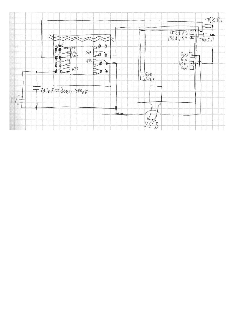
and a 333nF Ceramic Condensator (a 100nF would be better)
The RX-8025 was soldered on the Multiadapter by me and all items were mounted on a patch panel.
The wiring map shows the RX 8025 on the Multiadapter. Be careful to solder every second pin to the pin you put into the patch panel, because otherwise you have to build bridges from the pins which are not connected to the panel to free pins in the other row.
I attached the wiring. It is working quite good. I post it, because I don't find a complete wiring map on the internet.
I hope it will help someone who has the same problem.