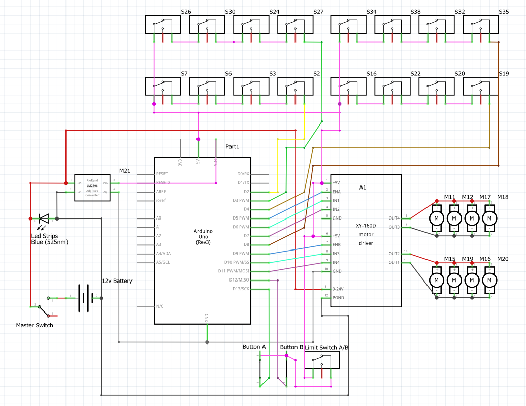
I'm making Jayce's hammer from Arcane for a cossplay and i've got the following circuit thought out using an Arduino and i was wondering if this is generally safe to build into my hammer or that i should maybe add a fuse somewhere or resistors to improve the working and safety.
A 12v battery pack directly connected to a master switch, powering a string (or 2 or 3) of 12v blue LED's, a XY 160-D motor controller and a buck convertor.
The buck convertor powers the Arduino.
It has a bunch of limit switches (2 for each motor on either end of travel) for safety and the total amount of motors is 16. If i was any good at using motors i could probably get away with a few less, but it is what it is. In the circuit i've only drawn in half of the motors and limit switches.
It also has 2 push buttons connected to another limit switch to control the motor action.
I've not yet wrote the code but it's pretty straight forward; When one of the push buttons is pressed, the motors either move clock- or counter clockwise, if one in a group of limit switches is tripped, the motors stop., preventing any movement in that direction.
Verify what's the actual voltage of your battery from full to empty. For 3S li-ion it would be ~9-12.6V. Is that ok for your motors/LED string? Is your battery discharge rate ok for the total motor current? Can your driver handle the needed motor current?
You need pulldown resistors for all of your switches inputs. Your LED symbol is backwards.
Also make sure your battery pack has protection circuit needed for safety!
Not necessarily. Wire C pin to GND and NO pin to the Arduino digital pin, and make things easier with the ezButton library.
That library defaults to using the Arduino built in pullup resistors and sets debouncing time in setup.
Safe as in will you get electrocuted? Yes, it's safe, just be sure to prevent any possibility of a battery dead short. The hobby RC car world would have lots of options for lipo batteries that will last for the duration of a Con, as well as staff who can advise you on an appropriate charger and general lipo safety related to fire risk.
I was looking at what this is (I don't play that Arcane) and I'm trying to understand what all these motors have to do with a hammer. Can you elaborate on your overall design goal?
In general, should be good, don't forget a ground lug (all grounds connect together).
Automotive supply houses are a good place to find suitable gauge wiring (I'd go 14AWG at least, depending on how many motors run at a time) and for a durable project that gets tossed about in the car trunk and generally used, switches, fuses (yes, use one between the battery and the main power switch).
I'm also wondering how you came to 16 motors in a giant hammer. What am I missing here?
If you aren't good with using motors, it isn't what it is. What it will be will be a nightmare to get working correctly. Get one working first and build up from there. Have you ever built a drone from scratch? This is like making four drones all work together. Not exactly an easy task.
I've changed the switches to use ground and INPUT_PULLUP. I'll add a fuse.
As for the function of the motors, i'm emulating this action:
First, move the lever closes the limit switch connected to both buttons so they can be used. Then pressing the A button will cause the motors to spin clockwise and
Have the head expand sideways.
Then move the front and back side away from each other
Then pivot the top and bottom parts on each side away from each other.
I might change it to have the limit switch directly operate the opening mechanism, but that's a small change depending on how the mechanism is working.
I'll have the motors on a timed run, but the limit switches are there for safety; when the motor expands the head and somehow reaches it's end of travel, a limit switch will be tripped, stopping the entire operation.
The other button will do the same thing but in reverse, so it will close up the head.
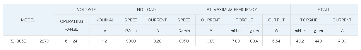
Annoyingly i do not know the max amp draw for the motors, it's not included in the Amazon listing.
And the reason i need this many motors it that i can do the 1 and 2 operation with 1 motor, but need a second one for the 3rd one. And with 8 pieces on the head, that's 16 motors in total.
Your circuit design looks solid, but for safety, I recommend adding fuses between the battery and components. Just like the motor controller and buck converter to prevent overcurrent.
You need to make sure the proper resistors for the LED strings and use appropriately gauged wires to handle the current.
Plus, you can consider an emergency kill switch and heat management for your motor controller. Hope your project goes next level!
Changed the url for the battery, these are the motors:
Specifications:
Product Name: DC Micro Motor
Model: 385
Voltage: DC 12 V.
Speed: 10,000 rpm.
Color: silver
Motor diameter: 27.5 mm.
Total length (including shaft and pin): 60 mm.
Shaft diameter: 2.3 mm.
Weight: 61.9 g.
Did you consider using servos for much of the action? Far easier than DC motors with limit switches and timed action. With servos, the feedback is built in and duplication of travel is a snap. Plus, using push/pull rods or other linkages makes it easier to mechanically connect to the work piece.
What are you housing all this in? I mean, what hammer do you have to modify or are you scratch building or 3D printing one?
Take a look at the RC hobby world, airplanes for how they control the rudder and ailerons with servos and pushrods, see if it gives you any ideas. 16 motors, phew, that's quite an ambitious project.
Tried it with a few servos i had around, it didn't have the oomph required at the speed i want. That's also the reason i went with 12v, that and 12v blue leds are bright, just what i need.
And yeah, 16 motors look like a challenge, but it's basically 8x the same setup. When i get one setup working with just 2 motors, the others are easy.
But we'll see if i made a correct choice when i assemble everything
It's 90% 3d printed btw, some foam pieces to fill at a lower weight and easier production.
Estimating, actually based on a couple of other 12V 385 size toy/micro motors I Googled. The HALJIA company doesn't seem to offer a complete datasheet that I could find.
In any case, 16 * let's say 6A = 96A total at stall assuming all are running simultaneously. There's no way these are pulling more than 6A, I'm being overgenerous here, there's no way a brushed DC motor armature at less than 3cm diameter would handle that without the wire tabs melting off.
So, if OP was to select a lipo, something like a 3s, 4000mAh, 30C battery would allow for continuous discharge rate of 120A, 240A burst and if it was a 5000mAh, 50C 3s, it's 250A continuous, 500A burst.
The motors in question here aren't 540 size rock crawler cans or brushless drone motors. It'll be fine with the right battery.
As for the motor driver, that's another question.
For wire, automotive wire is a good choice or sticking with the RC hobby options designed for high current applications, something like this is a great choice:
Without knowing anything about the batteries and the actual current draw by the motors, I can't see how anyone including myself can tell you it will be 100% safe.
You obviously have concerns, otherwise you wouldn't be asking.