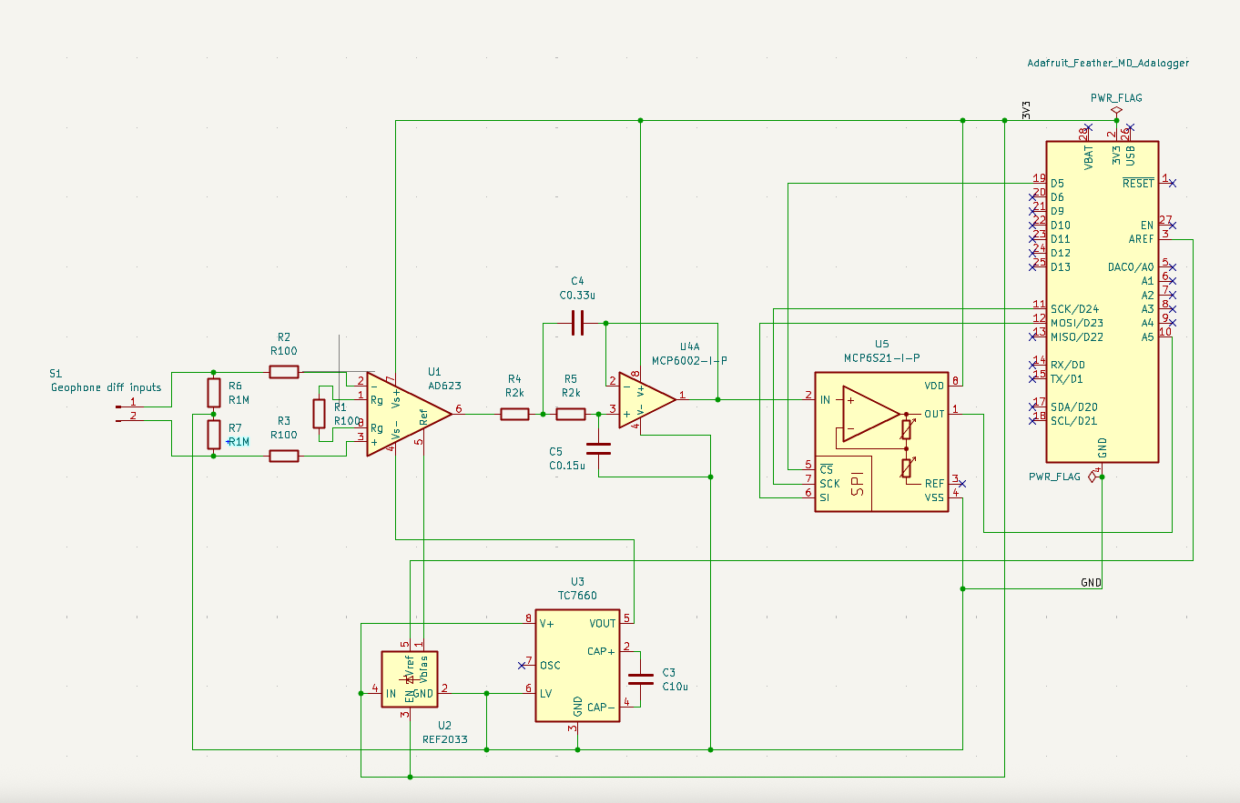
I'm hoping someone can help spot what is up with my schematic. I am taking a geophone differential signal, passing it through an in-amp AD623 (±3.3V) and then applying a low-pass Sallen-Key Butterworth filter (Vdd = 3.3V, Vss = GND, Fs = 357Hz, Q = 0.74). I apply a mid supply bias to the Vref pin on the in-amp, this comes from a REF2033AIDDCR. If I measure the signal immediately after the in-amp, the signal has the correct bias (1.65V) but after the filter, it has dropped to around 1V. This is my first foray beyond breakout boards so I am sure I have missed something quite simple!
5 unconnected wires are shown at the top of your schematic. Another 5 unconnected wires are shown on the right side. These wires need to be connected to something for the circuit to work correctly.
Am I understanding you correctly, you have a problem you can't solve, but at the same time have decided it can only be in a particular subset of the circuit?
Thank you for this but the geophone inputs aren’t floating, the input symbol isn’t clear but I’m using a two wire connector block which will be connected to the relevant ± outputs from geophone. I’ll take a look at those schematics for some inspiration though.
Why do you think that? There is nothing on the inputs to define their DC reference levels, therefore they are floating. Look at the examples @jremington provided.
You have now told 2 people who are (were) trying to help you that they are wrong. Both those people have the experience and knowledge you came here for, please don't tell me I'm wrong too.
I haven’t told anyone they are wrong, I have tried to clarify whether it was a misunderstanding over the symbol used. Equally happy to post the full schematic but I’m not going to tolerate rudeness, I’d rather work it out on my own.
We get people posting only the "relavent" parts of their code on a daily basis. Around half the time, the problem turns out to be in a part of the code they didn't think was relavent, which is why they didn't spot it themselves.
If you think there is DC to be removed where do you think it's coming from?
If there were DC to be removed then 1 capacitor would do the job because the components are all in series so it doesn't matter where the capacitor is, so one will do. However, this is only true if the wires from the geophone are short. If they were a long twisted pair then your 2 capacitors would be correct in order to maintain balance, but, are capacitors needed at all? See first comment.
Removing DC isn't your problem, (not) adding the correct DC bias is.
Thanks Perry, I was thinking it would be prudent to clean the signal (?) but yeah, I guess that doesn’t make much sense if there’s no DC to be removed in the first place. I’ll remove those caps and add a ground source to the differential inputs, see if that helps. Thanks again
I’ve added ground coupling via 1M resistors which I realise is a bit more than that first schematic but found a tech note recommending using higher values (TI application note). Also removed C1 and C2.
Unfortunately seeing the same behaviour. Correct mid supply bias (1.65V) immediately after the in-amp but then dropping to around 1.2V after the RC filter.