I have this custom board that uses a SAMD21 MCU and (so far) most closely behaves like an Arduino Zero. I have been using boards similar to this one (also programmed as an Arduino Zero) in other projects, so far without issues. Now I have this problem.
This particular board has a LoRaWAN chip connected via a pair of UART pins to the SAMD21. It is supposed to use pins 15/16 (PB08/PB09) for TX/RX respectively. However, I have been unable to get an answer from the other side no matter how I configure the pins. Below is my sample program that is supposed to bridge the debug uart and the problematic uart together:
#include <Arduino.h>
#include "wiring_private.h"
#define DEBUG_SERIAL SerialUSB
#define PIN_TESTSERIAL_RX (16ul) // PB09
#define PIN_TESTSERIAL_TX (15ul) // PB08
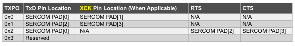
#define PAD_TESTSERIAL_RX (SERCOM_RX_PAD_1)
#define PAD_TESTSERIAL_TX (UART_TX_PAD_0)
Uart TESTSERIAL(&sercom4, PIN_TESTSERIAL_RX, PIN_TESTSERIAL_TX, PAD_TESTSERIAL_RX, PAD_TESTSERIAL_TX);
void SERCOM4_Handler() { TESTSERIAL.IrqHandler(); }
// EDIT: 2025/07/09 this macro definition is a copy-paste error and was not supposed to be active.
// #define TESTSERIAL Serial1
void setup()
{
DEBUG_SERIAL.begin(115200);
uint32_t t1 = millis();
while (!DEBUG_SERIAL && millis() - t1 <= 100);
TESTSERIAL.begin(9600);
pinPeripheral(PIN_TESTSERIAL_RX, PIO_SERCOM_ALT);
pinPeripheral(PIN_TESTSERIAL_TX, PIO_SERCOM_ALT);
}
void loop()
{
int c;
while (TESTSERIAL.available()) {
c = TESTSERIAL.read();
if (c >= 0) DEBUG_SERIAL.write((uint8_t)c);
}
while (DEBUG_SERIAL.available()) {
c = DEBUG_SERIAL.read();
if (c >= 0) TESTSERIAL.write((uint8_t)c);
}
}
By searching through this very forum, I found a post asking for exactly this scenario: SAMD21 SERCOM Serial1 & Serial2 not working . The post was closed in May 2021 without any satisfactory answer.
From what I can gather from the variant.[h|c] files, sercom4 is supposed to be already in use for SPI. My particular project does not make use of SPI, and I am perfectly fine with disconnecting any conflicting SPI functionality, as long as I can use an UART on those particular pins (that is, pins 15/16). Also, those pines are marked as "analog pins" A1 and A2. Again, I do not use analog pins on this particular project, and I am fine with disconnecting anything that conflicts on those pins.
The board can be physically patched to move the LoRaWAN connections to the pins matching Serial1, and has been done for one board. However, this is but one of a batch of boards and I would not like to have all of the boards patched if this can be fixed in firmware instead.
Why would the above program not work in my setup? Am I missing some step? Are the steps done in the correct order? Do I have to explicitly rip out SPI and/or analog functionality from the target pins in order to initialize the UART?