Can anyone be of help on how to connect the wiring – where to plug the servos - how to set all up, in order to be able to record / sample (datalog) the position of servo movement for elevator, aileron, rudder and flap position during flight with a model aircraft. The purpose is of course afterwards to be able to see the position of the servos for each of the channel. I would imagine a sampling rate every second (perhaps less) for each of the channels.
I presume that something like this must have been done and performed before which is why I hope for some advice / help here.
I have been searching the Forum on the subject and the only “thread” close is one from April 2022, but as I see it it´s not quite what I am looking for.
Another one I found is this which looks interesting:
Here potentiometers are used – (replace them with the onboard servos) - and connected to the Arduino so my question is, how do I connect the servos to both the Arduino as well as to the rc receiver on board the model aircraft.
Tap into the servo signal before the servo. The digital inputs on most Arduino compatible processors have more than 10M Ohm input impedance so will not effect (load) the signal at all. If the servo signal is over 5V it will need conditioning. A resistor voltage divider can be used.
There are many tutorials on the net about how to read servo signals with an Arduino. Often using the pulseIn() function.
I'd like to restate your problem statement, to see if I understand what you want to do, and we'll then see if you understand the nature of the problem you're faced with.
able to record / sample (datalog) the position of servo movement for elevator, aileron, rudder and flap position during flight with a model aircraft. The purpose is of course afterwards to be able to see the position of the servos for each of the channel. I would imagine a sampling rate every second (perhaps less) for each of the channels.
Rephrased as,
I'd like to record the positions of servos in my model aircraft. The servos are controlled by a separate device, which issues PWM signals to the servos independently of my Arduino. The PWM signals must be monitored in real-time to reflect control surface changes that happen infrequently but asynchronously. Those changes must then be recorded, along with time stamps to allow flight reconstruction.
I hope you see where I'm going with this. The PWM signals are nothing like those potentiometers in your example code. Instead, they are pulse widths, which your Arduino code must measure and store for comparison from code cycle to code cycle, watching for changes that may represent control changes(or may represent insignificant signal width variations), and writing to storage all changes deemed significant, along with a time stamp for each. Not a trivial task, though not insurmountable.
Doing this would be SO much simpler from within the device emitting the PWM signals.
: looking for signs of life from @rcmodeller - you out there? Does this make sense?
Sure there is. You just reference everything back in time from the point when the collision detector... detects terra firma. Maybe, add a GPS readout for flight location/direction data.
The sky's the limit!
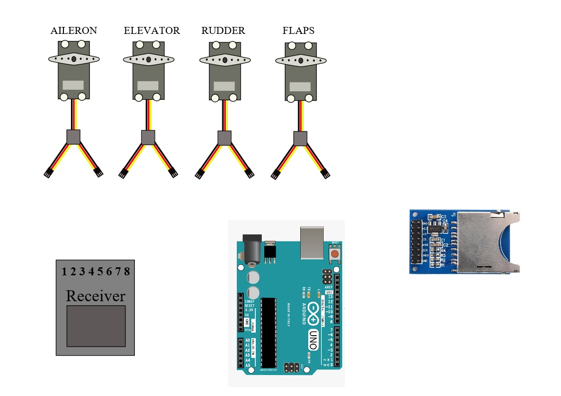
The easiest way to tap into the signal to the servos is to use a “Y” connector. These are used to connect two servos to one receiver output. You will only need to use the ground and signal wires. In fact you will only need one ground wire from the receiver. You will need one for each servo.
You will have to limit the peak input voltage as mentioned above. The need for this will depend on the voltage your receiver is operating at. For example, a receiver on an electric plane using 5 volt power from a BEC or the ESC, assuming you are using 5 volts to power the Arduino. A resistive voltage divider or other voltage reducer such as a diode or zener diode and resistor will have to be used for higher voltages. If you have an oscilloscope or volt meter that can read peak voltage you could measure the actual peak voltage output of the receiver to determine if you will need attenuation or not.
I have lots of R/C experience but am a noob on Arduino so I will leave the rest of the solution to the other.
I found this and a few other sites that say newer receivers output 3.0 or 3.3 volt pulse amplitude so I would say that checking the voltage level would be strongly recommended.
That´s what I had in mind, using a “Y” cable, but wasn´t quite sure so I´ll go for that. Firstly I´ll have to look much more into Arduino for as you see, we are obviously at the same level, you with lots of R/C experience and me with nearly 60 years of R/C flying, but when it comes to Arduino I´m a novice trying to learn every day. Thanks for you input.
So you have your hardware answer. Now, on to the software. Have you considered my previous comment about pulse vs pot? If you had access, you could record the internal feedback potentiometer value within each servo(though that might be a bad idea, introducing noise to those signals would cause havoc). As it is, with your 'Y' cable, you'll need to adopt the strategy I've described.
Please identify how many servos we're talking about, and we can begin to discuss a solution.
I definitely like your rephrasing of my text, which is exactly what my intension is – to allow for a flight reconstruction – to be able to see how much deflection on each servo at a specific time. In the late 1970´s I made a “poor mans telemetry” setup with an extra receiver + servos - ground based and with writing pens connected to each servo. These servos would then work in unison with the ones onboard the model and write with ink on a time-controlled paper roller band. I remember there was an article in the magazine R/C Modeller which is where I copied it from. Those were the analog days, so now I´ll have a go at some sort of a digital setup, which is why I had Arduino in mind.
This is needed. Also, consider what defines "start record" and "stop record". Will a simple digital input suffice to enable/disable, or something else?
@groundFungus pointed you at the pulseIn() function. Have you reviewed it?
What Arduino are you contemplating using, by the way?
mmmmm....well, in my experience at flying r/c models ( and that quite a long time now) any crash is usually due to pilot error regardless of the amount of denial.
As well, a factor in the crash is usually inversely proportional to the amount of aux electronic equipment to assist or to monitor flying that is contained onboard.
The control actions alone will never be enough to determine the cause of a crash. A real black box also records aircraft attitude, altitude, airspeed etc. @rcmodeller has not even stated their reason for wanting this data. I would not assume it was for crash analysis. Perhaps they want to review what they did on a particularly successful flight.
Flight time, position is totally irrelevant for my purpose – it´s merely to be able to see the position of each of the servos after a flight, nothing else. It has nothing to do for me duplicating a flight or be able to analyze an eventual crash.
4 servos.
”start record” and ”stop record” – well, nothing specific in mind – I guess from start to finish of flight ?
I intend to use a UNO and a SD card reader.
No, it has nothing to do with crash analysis. As I pointed out in my first post:
“The purpose is of course afterwards to be able to see the position of the servos for each of the channel.”
That´s all there is to it. Time, position for the flight – doesn´t matter and is of no importance to me at this point.
For those obsessing about my comment about terra firma, it was a simple wisecrack in response to the post of another. Sheesh.
As I described earlier, measure the pulse width of each of the four signals and record those if they change beyond a predetermined deadband. Do that round-robin, saving each change to SD, along with a millis() timestamp, if it's warranted. You must determine what is a significant change, and how frequently to measure and save.
Not optimal with an Uno, as your pulse width measurement will be 4uS increments, iirc if you use micros(), not sure what can be done if you use a hardware timer, but it's a start.