Ok, thank you. Sometimes it does not output any number when I click. How do I fix this?
I don't know. Are you getting all the 0-15 numbers somewhere? Or is there a pattern to what is missing? Do you get the number of you click a notch back and forward again. If there's a pattern to some missing numbers, maybe there's a wiring problem.
I'f it is just one missing number, maybe the part is bad or the detents don't match the contacts..
It's hard to say without data.
I tried implementing this "working" code from a different example, but for some reason there are regions that give nothing but zeros.
#include <stdio.h> // Not sure if this is necessary

const int dialPin1 = 8; // Labeled "1" on encoder
const int dialPin2 = 9; // Labeled "2" on encoder
const int dialPin3 = 10; // Labeled "4" on encoder
const int dialPin4 = 11; // Labeled "8" on encoder
// Declaring all variables
int dialVal1 = 0;
int dialVal2 = 0;
int dialVal3 = 0;
int dialVal4 = 0;
int dialAbs = 0;

void setup() {
  delay( 3000 ); // Let the Arduino wake up :)
  pinMode( dialPin1, INPUT_PULLUP );
  pinMode( dialPin2, INPUT_PULLUP );
  pinMode( dialPin3, INPUT_PULLUP );
  pinMode( dialPin4, INPUT_PULLUP );
  Serial.begin( 9600 );
}

void loop()
{
    dialPos();
    Serial.println( dialVal1 );
    Serial.println( dialVal2 );
    Serial.println( dialVal3 );
    Serial.println( dialVal4 );
    Serial.println( dialAbs );
    Serial.println("------"); // For visibility
    delay( 2000 ); // Keep that Serial monitor slow
}

void dialPos() { // determine position based on output of each pin
  dialVal1 = !digitalRead( dialPin1 );
  dialVal2 = !digitalRead( dialPin2 );
  dialVal3 = !digitalRead( dialPin3 );
  dialVal4 = !digitalRead( dialPin4 );

  dialVal3 ^= dialVal4;
  dialVal2 ^= dialVal3;
  dialVal1 ^= dialVal2;

  dialAbs = dialVal1 | (dialVal2 << 1) | (dialVal3 << 2) | (dialVal4 << 3); // Bit shifting
}
If you line them up at A0, A1, A2, A3 you can read them in one go:
byte tempIn = PINC & 0x0F; // read the encoder, 4 bits
A print here will allow you to read the numbers to build the grayTable.
Now you use the array:
newPosition = grayTable[tempIn]; // translate to position, mind the square hooks
It can even be combined:
newPosition = grayTable[PINC & 0x0F];
Setting the pull-up resistors is also simple:
PORTC |= 0x0F; // pull-ups at A0 A1 A2 A3
Declaration of the table:
byte grayTable[] = {0, 0x01, 0x03, 0x02, … }; // example, adapt to your encoder, needs 16 numbers, either hex or decimal
If the bit that is changing bounces, the difference will be only 1 step in the position, that is the advantage of Gray Code.
This is not necessaraly portable to another board anymore, but adapting is easy.
If you still use pins 8, 9, 10, 11 make it PINB and PORTB.
What do you get for all of the the raw values around one revolution?
Up here it sounded like you got most/all of them:
How many ticks are there in a revolution? A gray code should change by 1,2,4,or 8 with each step. If you've got 8 ticks around the circle, I could understand observing a change of 5(=4+1) in between adjacent ticks. If you have 16 ticks and 16 different raw numbers, the hardware is OK.
I wrote my code based on your advice. I am almost getting something meaningful. Problem is still that sometimes I get no reading, and other times I get two different readings printed out in the serial monitor at the same time for the same position.
My array: [5, 15, - , - , - , 14 and 4, 6, 2, 0, 3 and 15, - , - , - , 9 and 1, 3, 7]
My code:
bool bit1=0;
bool bit2=0;
bool bit3=0;
bool bit4=0;
int lastCode=-1;
int newCode;
const int pin1=A0;
const int pin2=A1;
const int pin3=A2;
const int pin4=A3;


void setup() {
  // put your setup code here, to run once:
  pinMode(pin1,INPUT_PULLUP);
  pinMode(pin2,INPUT_PULLUP);
  pinMode(pin3,INPUT_PULLUP);
  pinMode(pin4,INPUT_PULLUP);
  Serial.begin(9600);
}

void loop() {
  // put your main code here, to run repeatedly:
  bit1=digitalRead(pin1);
  bit2=digitalRead(pin2);
  bit3=digitalRead(pin3);
  bit4=digitalRead(pin4);
  newCode = bit1<<3 | bit2<<2 | bit3 <<1 | bit4;
  if (newCode != lastCode) {
    lastCode = newCode;
    Serial.println(newCode);
}}
Add a small delay in the loop, like 50 milliseconds.
a7
I suppose the "-" entries remain at 15? Maybe the ground is poor somehow and in those locations, the ground-wiper isn't pulling down any of the contacts, leaving the pins all pulled-up HIGH?
Looking at the datasheet, 30000 cycles minimum life would be 50 minutes of operation at 600rpm. Could the encoder be worn?
Maybe for the 14&4, 3&15, 9&1 there's some bouncing? Perhaps add a delay(5) to make the polling less likely to happen at transitions.
No, the '-' entries correspond to nothing printing in the serial monitor. I can go back the other way to the same position and still nothing will print. Also the max rpm is 600, I only need it to track a slowly rotating shaft position. I have a brand new identical one and it does the same exact thing. I will try the delay(5) in a while.
Several positions give the same reading. The encoder has only 5 pins. It is possible that the datasheet belongs to another variant, and the designation of the pins is wrong. I would expect that the pin that stands away from the others is the common. Keep trying till you found the right pin that is the common.
If two adjacent detents produce the same 15 bit-code value, the code wouldn't notice a change and wouldn't print a newCode.
15 is an interesting value because it could mean none of the pins are being grounded. Are you certain you haven't switched the common with one of the other contacts on the encoder? That could make everything HIGH and cause odd problems.
Here's a Wokwi simulation where one would toggle the switches to produce a gray code:

https://wokwi.com/projects/384136329791339521
// https://wokwi.com/projects/384136329791339521
// for https://forum.arduino.cc/t/setting-up-a-16-position-absolute-rotary-encoder/1200508/10?u=davex
const byte gray1 = 8;
const byte gray2 = 9;
const byte gray4 = 10;
const byte gray8 = 11;


bool bit0=0;
bool bit1=0;
bool bit2=0;
bool bit3=0;
int lastCode = -1;
int newCode;
// per https://en.wikipedia.org/wiki/Gray_code
int untangled [] = {0,1,3,2,  7,6,4,5,  15,14,12,13, 8,9,11,10};

// From https://en.wikipedia.org/wiki/Gray_code#Converting_to_and_from_Gray_code
typedef unsigned int uint;
// This function converts an unsigned binary number to reflected binary Gray code.
uint BinaryToGray(uint num)
{
    return num ^ (num >> 1); // The operator >> is shift right. The operator ^ is exclusive or.
}
// This function converts a reflected binary Gray code number to a binary number.
uint GrayToBinary(uint num)
{
    uint mask = num;
    while (mask) {           // Each Gray code bit is exclusive-ored with all more significant bits.
        mask >>= 1;
        num   ^= mask;
    }
    return num;
}

void setup() {
  // put your setup code here, to run once:
  pinMode(gray1,INPUT_PULLUP);
  pinMode(gray2,INPUT_PULLUP);
  pinMode(gray4,INPUT_PULLUP);
  pinMode(gray8,INPUT_PULLUP);
  Serial.begin(9600);
}

void loop() {
  // put your main code here, to run repeatedly:
  bit0=digitalRead(gray1)==LOW;
  bit1=digitalRead(gray2)==LOW;
  bit2=digitalRead(gray4)==LOW;
  bit3=digitalRead(gray8)==LOW;
  newCode = bit3<<3 | bit2<<2 | bit1 <<1 | bit0;
  if (newCode != lastCode) {
    lastCode = newCode;
    Serial.print("Gray:");
    Serial.print(newCode);
    Serial.print(" 0x");
    Serial.print(newCode,HEX);
    Serial.print(" 0b");
    Serial.print(newCode,BIN);
    Serial.print("  \tLookup:");
    Serial.print(untangled[newCode]);
    Serial.print(" \tGrayToBinary:");
    Serial.print(GrayToBinary(newCode));
    Serial.println();
  }
  delay(3); // comment to see effect of bouncy switches
}
If you have 1 detent per position, each position change should move the gray code result by 8, 4, 2, or 1, so your 4, 6, 2, 0,15 looks healthier than your 5,15 transitions.
Which actually makes a nice nerdy puzzle:
Try to flip the switches in the correct order to get the lookup sequence 0..15 in order… took me one try, guess it's all the Tower of Hanoi puzzles I've done. ![]()
a7
1 Like
Here is an image of my encoder:
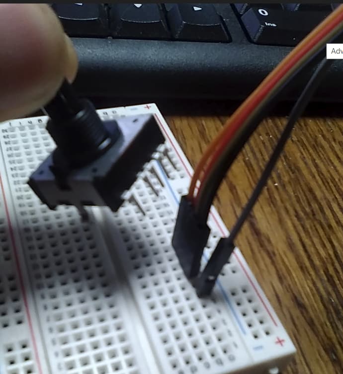
I have the outstanding pin setup to the Arduino ground. The four "A" pins are connected from Arduino to the four on the encoder.
More pics:


The datasheet says the middle pin is the common. Which one is true? Maybe neither.
1 Like
Between the data sheet and some guess based on the pin geometry, I'd go with the data sheet.
Which, BTW, doesn't even list the weights of the four switches.
a7
1 Like
@stitech @alto777 @DaveX I am now getting a different value for each encoder position. I had the ground in the wrong spot. I would've never guessed that the common is in the middle. I am now trying to make the lookup table to get my sequential values. Thanks for the help!
1 Like


I hope at an appropriate time you can post a good schematic and functioning program, from which the weights (8, 4, 2, 1) of each switch contact can be determined.
That nifo is not in the datasheet, as far as I can read one, and means everyone working with that encoder goes through, if not the trouble you had with the odd common pin location, then certainly with the assignments of the four contacts.
TIA!
a7
I have merged your topics due to them having too much overlap on the same subject matter @remusconnor.
In the future, please only create one topic for each distinct subject matter and be careful not to cause them to converge into parallel discussions.
The reason is that generating multiple threads on the same subject matter can waste the time of the people trying to help. Someone might spend a lot of time investigating and writing a detailed answer on one topic, without knowing that someone else already did the same in the other topic.
Thanks in advance for your cooperation.
1 Like