I am in the process of building an Arduino powered 16 x 7 LED clock. I am currently working on getting the idea of the wiring right so that when I actually start putting it all together I have something to look at. I am just wanting to get some other opinins and see if anyone has any suggestion on how I could make this more efficient or let me know if it is good as is. Thanks for any input!
You have 1 capacitor in there.
Use a 100nF capacitor real close to any of those 595's, so 3 pieces.
Also, you seem to plan to have all 3 displays show the same content.
You have created one double loop (the light green line) that is connected to all 3 595's.
Loops can be very interesting, but i don't think you're looking for that at the moment.
And 2 (blue and purple) other lines that are connected to all 3 of the 595's also.
That means you are sending the same data to all 595's without any addressing or distinction what data is meant for what 595.
I think you want to connect the 595's in series.
That means the first one gets its data, and will overflow into the second one that will overflow into the third one when receiving data.
The 595 has a data out pin (pin 9) for that.
So you send 3 bytes to the first 595 and the first will end up in the 3rd 595, second in 2nd and third in 1st.
Do you mean a matrix of leds 16 wide by 7 high? Or 16 x 7-segment led displays?
Either way, you are going to have a problem. Each output from a 595 can either source or sink enough current for a single led. But they cannot source or sink enough for a group of (either 7 or 16) leds. You will need an extra chip for that, or some transistors. You could:
replace one of the 74hc595 with a tpic6b595, which can sink (not source) much more current per output
add a uln2803 to one of the 595s to boost its current sinking capability
add 8 transistors to one of the 595s to boost its current sinking (using pnp transistors) or sourcing (npn transistors) capability
replace all 3 595s with 2 x max7219 led driver chips
In many ways, option 4 is the simplest, less hardware and less software will be needed. There is an Arduino library to help you control the 7219s.
Thanks for both of your input! I clearly have a lot more to work on, I am still kind of new to all of this but I am slowly getting the hang of it. I'm trying to keep the project as streamlined as possible. And btw it is 16 wide by 7 high, individual LEDs. I know its a random number but while building the case I was off with my measurements so I just added some more rows and columns. It was originally going to be 15 x 5.
I did figure if I wanted to stay with the current configuration I would probably need some transistors but I wasn't sure where to put them.
So if I stay with the 3 595's (I've already ordered them) should I add a capacitor to each 595 and 8 transistors to just one 595(option 3 from Paul) or 8 transistors to each 595 as well?
@MAS3: yes you are correct I am wanting to connect them in a series, so would I just link the 2nd 595 to the 9 pin of the 1st and then the 3rd 595 to the 9 pin on the 2nd?
Lastly, I've included a picture of the 'frame' it will all be in, so maybe this will help you see what I am trying to accomplish.
Hi, your picture raises more questions than it answers! Are those copper wires meant to carry current? If so, how will you stop them shorting from rows to columns?
For transistors, you will need at least 7, one each to handle the current for a row of 16 leds. The brightness of the leds will be limited by the total current the 595s can handle, only about 80mA, so 10mA per led. If that's not bright enough (remember each leds will only be lit for 1/7th of the time), you may need another 16 transistors, one for each column.
What leds have you purchased? What colour, forward voltage and max current?
Ha! Yea, I know it looks like a mess. The copper wire row & columns are actually about a quarter inch apart. It's kind of hard to tell from the picture. I am working on a new schematic right now to show how I will hook up all the transitors, I think I am going to err on the side of caution and use a resistor for each row and each column [23 total].
As far as LEDs I haven't purchased them yet, originally I was cannibalizing them from Christmas lights but that has turned out to be a pain so I am going to buy new ones. I think I am going to go with blue or green. Do you have any suggestions as far as forward voltage and max current? I honestly have no idea which kind would be best, I do know I would like to use 5mm though.
Go for high brightness to make the best of the current the 595s will be able to supply. Green seem to have slightly higher apparent brightness, to the eye. Both blue and green high brightness tend to have a forward voltage around 3.2V and max current of 20 or 30mA, but you may be limited to 10mA anyway because of the 595s.
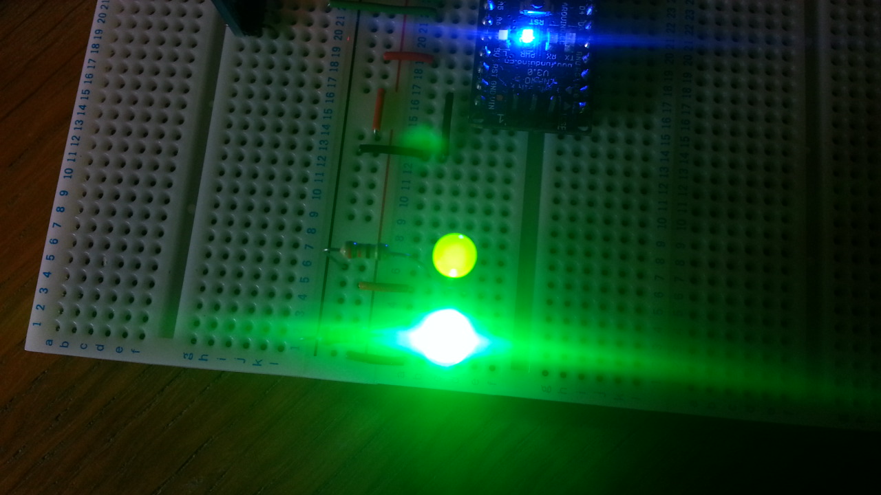
High brightness leds are usually made of clear plastic, so if you want to disperse the light more, you may have to sandpaper them first. Don't go for the older green type just because they are diffused, their light output is very disappointing by comparison (they have a forward voltage of only around 2V). In the picture below, the old-style led is drawing 8.2mA, the new high brightness led is drawing 5.5mA.
Also don't be tempted to go for the cheapest leds you can find on eBay. I learned this the hard way! Replacing an led that has died somewhere in the middle of the led cube you have carefully constructed is no fun. Avago are a good brand, for example.
Sorry it has taken me so long to get back on here, I have been busy trying to support my hobby. Anyway, I have switched from doing individual LED's to using 7-Segment Common Cathode Displays (4 of them). I have started the schematic and just wanted to get some opinions again before I finish it. I have a resistor in between each output of the 595 and the inputs for the 7-segment, they will be 220 ohm, and the resistor in between the the transistor and the 595 ( no. 4) will be 1k ohm. How does this look?
If you have one 595 to drive each 7-seg display, you do not need to multiplex, and do not need any transistors.
Alternatively, you can use only 2 x 595s and 7 or 8 transistors (or a single ULN2803) and use multiplexing. But I would recommend using 4 x 595 over multiplexing. Multiplexing will reduce the average current down to 2.5mA per segment, v. 10mA if you don't multiplex.
Your circuit above seems to be somewhere between the two ideas, but because you haven't completed the wiring, I can't tell which approach you are trying to take. So please explain a little more: multiplexing or not?
Also, what is the forward voltage (Vf) and max current of those 7-seg displays? Your series resistors should be calculated from those figures, but also to avoid overloading the 595s.
If you are open to design changes (and I think you are given you have abandoned your original dot matrix design), I would suggest simplifying by using a single max7219 or saa1064 driver chip instead of the 595s.
Thanks for getting back so quickly! Haha, my brain hurts, I feel like this should be easy but I keep getting hung up. Okay, so I will not need the transistors because I will be using all 4 595's, not multiplexing, right? Also the max forward voltage for the segments is 30mA and the voltage is 2B [typical 20mA & 1.7 V]. The figure that I got for the resistors was 100 @ max and 165* @ typical, but everything I could find online everyone was using 220 ohm resistors for some reason.
Also, are the capacitors placed correctly. I found a few different ways that people had them hooked up, this one just seemed to make sense to me. Also, above someone suggested I place one in between BBC and GND, yea or nea?
... As far as design changes I am totally open but I already have the 595's so I'm just gonna use them. I'm just ready to get this thing complete, haha. For future purposes though I will definitely try those other suggestions.
OK, so no multiplexing. Keeps the sketch and hardware simple and your displays nice and bright.
Mr_Pettit:
the voltage is 2B [typical 20mA & 1.7 V]. The figure that I got for the resistors was 100 @ max and 165* @ typical
Can you clarify that please? Its confusing!
If your displays have a Vf of 2.0V and your Arduino is supplying 5.0V (via the 595s), you need to loose or "drop" the other 3.0V. The 595s can only supply around 80mA each so 10mA per segment. Now you need to use Ohm's law R = V / I = 3.0 / 0.01 = 300 Ohms. In practice, the outputs will probably be a bit less than 5V, especially when you draw 10mA, so you might get away with 220, but I would play it safe if I were you.
For those caps, yes, they go from 5V to GND. One per 595 chip, as close to the chip as you can easily get. If you are prototyping on breadboard (and I do recommend you do that), just put the caps across the breadboard's power rails next to each 595.
So on the package for the 7-segment it had the max forward voltage listed as 2.0V with the max current at 30mA. And the 'typical' listed as 1.7V and 20mA. When I put those numbers into a resistor generator I found online I got 100 ohm for maximum and 165 ohm for the 'typical'.
I used one of these 7-segment once before when I was just messing around and I had a 220 ohm resistor hooked to it and it was kind of dim. Not sure if it was something I did because it was the first project I ever tried, so it's very likely that it was user error.
And yes, I'm going to put it all together on a breadboard first. I made the mistake of not taking that important step before, no bueno. When I get home tonight I'll rework that schematic and post what I get.
Just out of curiosity are you into electrical engineering as a job or do you just tinker with electronics a lot because you seem to know quite a bit about all of this.
Mr_Pettit:
And the 'typical' listed as 1.7V and 20mA. When I put those numbers into a resistor generator I found online I got 100 ohm for maximum and 165 ohm for the 'typical'.
Problem is you can't afford 20mA per segment. 160mA would overload the 595. Look here (page 6) http://www.nxp.com/documents/data_sheet/74HC_HCT595.pdf.
"Icc supply current max: 70 mA"
So even 10mA per segment is over the limit, strictly speaking. The designers of the 595 did not really intend it to be used for driving leds like this. It was intended to be more of a general purpose logic chip, connected only to other logic chips. Otherwise they would have given it the ability to cope with more current. That's one reason why chips like max7219 and saa1064 are better this kind of thing.
Mr_Pettit:
I used one of these 7-segment once before when I was just messing around and I had a 220 ohm resistor hooked to it and it was kind of dim. Not sure if it was something I did because it was the first project I ever tried, so it's very likely that it was user error.
Maybe you connected it to the common cathode/anode and tried to light all 8 segments?
Mr_Pettit:
Just out of curiosity are you into electrical engineering as a job or do you just tinker with electronics a lot because you seem to know quite a bit about all of this.
Just a hobby, started 2 or 3 years ago, but my secret is that 25 years ago I studied Physics & Computer Science at Uni. Worked in IT and Retail in the years inbetween.