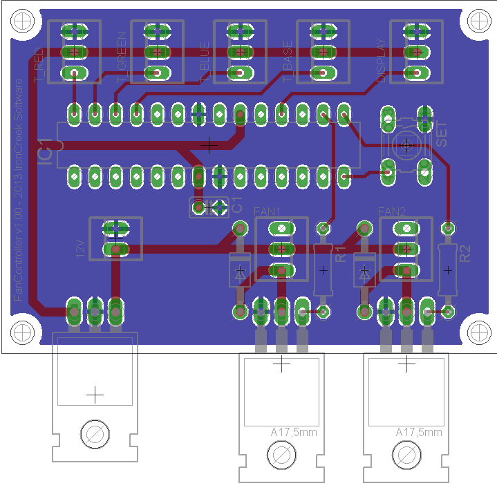
I've recently put together a prototype fan controller board (see attachment).
Now I'd like to create printed PCBs to do a larger production run.
Can you guys please sanity check the attached schematic and PCB layout for me?
I'm new to Eagle CAD and PCB layout, so I'm sure I did not take into account various considerations.
Please let me know if I'm missing something or need to place the components differently.
I have a few suggestions regarding your schematic:
Add a 1K resistor from atmega RESET pin to +5V.
Add a 6-pin ICSP header so that you can reprogram the chip in-situ.
Add a capacitor of 220uF or more from the +12V supply near the fan output pins to the emitters of the TIP120s.
Make provision for adding a pullup resistor from pin 14 to +5V, in case the wires to your switch pick up noise and the internal pullup resistor isn't string enough. [EDIT: I just noticed that the switch is mounted on the PCB right next to the chip, with a very short trace between them and a ground plane underneath; so this won't be necessary.]
[EDIT:] 5. Very important! Add the recommended input capacitor and (if applicable) output capacitor for the 7805. The capacitor I suggested at point (3) may be able to double up as the input capacitor, see what the regulator datasheet says.
dc42:
I have a few suggestions regarding your schematic:
Thank you so much for taking time to look this over!
Add a 1K resistor from atmega RESET pin to +5V.
Ok. Are you sure on the 1K?
I've looked for some documentation for this and the recommendation seems to be 10k or 4.7k
Add a 6-pin ICSP header so that you can reprogram the chip in-situ.
The board has to be reasonably small (without going SMD). I can't find a good place for the 6-pin header and more importantly, I can't find a place where I can run all 6 wires without crossing traces. I will solder in a 28-pin socket, so I can remove the chip for programming.
Add a capacitor of 220uF or more from the +12V supply near the fan output pins to the emitters of the TIP120s.
The TIPs are controlling CPU fans. I read that these already have the caps built-in. No?
Very important! Add the recommended input capacitor and (if applicable) output capacitor for the 7805. The capacitor I suggested at point (3) may be able to double up as the input capacitor, see what the regulator datasheet says.
Looks like the 7805 datasheet says 0.33uf. I shall add that.
I haven't checked your PCB layout.
Any input on that would be appreciated.
Thanks again for taking the time to look this over!
mmcp42:
there are tree places on the PCB where you have acute angles between tracks
change these to right angles
it will avoid etch eating away too much
Thank you as well for reviewing the design! Good tip!
I thought conventional wisdom said to avoid right angles.
But I can see your point that acute angles are much worse.
Updated board layout attached. Is this better?
Are "T" intersections ok?
int2str:
There is no reason why the ground plane shouldn't go all the way to the edge, right?
I'll fix that, too, I think...
You can leave just a little bit of space, Most PCB MFG places require a certain minimum distance of copper from the edge. Doesn't need to be a lot.
Did you leave enough space for the heads of the mounting screws? It looks like you might have, but it is close.
Possibly add exposed pads to the mounting screws for grounding to the chassis and an easy Negative reference point? Maybe unnecessary and not always desired, depends what the chassis is made from. I personally like it for the second reason I listed.
Alright, I incorporated all of your feedback (hopefully).
Also switched to the ATTiny85 and using the 1-Wire bus for the temp sensors.
Can you guys please look it over once more and make sure I didn't do anything silly?!
Also, since doing these is not my day-job, any tips for how I did the schematics or the board layout? Anything that is not "industry standard"? Anything I should read up on regarding schematics and board layout?
T intersections are fine
why not add another "earth" plane on the top as well
saves etching excess copper
also looks like you have an unrouted segment between C2 and R1
if it is really routed, hide top and bottom layers, delete the unrouted then reveal top and bottom!
On another note, it's probably a bad idea to do a large production run in the first place without first getting a few boards to test beforehand. You can get 10 bds for $100 from US companies, or for much less than that from places in CN. I know a guy who didn't do this, and now he has 5000 unusable PCBs in a box in his closet.
I have one more comment (in addition to my earlier ones): why are you using a large voltage regulator in a TO220 case, when you are only drawing a few milliamps from the +5V supply? I would use a small regulator in a TO92 or SMD case, such as 78L05.
mmcp42:
also looks like you have an unrouted segment between C2 and R1
if it is really routed, hide top and bottom layers, delete the unrouted then reveal top and bottom!
Thanks! Eagle eyes
dc42:
I have one more comment (in addition to my earlier ones): why are you using a large voltage regulator in a TO220 case
The three TO-220's are all mounted to a common heat sink rail (with proper isolation).