I’m interfacing an SCT-013-030 sensor with an Arduino Mega 2560. Using this schematic and sketch, I’m receiving the values expected compared to a Kill A Watt P3 meter. I realize the P3 isn’t the most accurate device in the world, but it’s what I have and it displays consistent values, so even if it’s off a slight amount, it’s good enough for my application.
The issue I’ve run into is that once the simple logic is incorporated into a more complex circuit, which includes a 2.42 OLED display, the values change depending on if the screen is on or off, by about .4 amps.
Is this a case where I need to incorporate AREF connected to an external known voltage to keep the readings accurate?
The two resistors are 10k, and the capacitor is a 10uf.
5volt on USB power could vary a bit under different loads.
You could
Power the Mega externally with 9volt on the DC socket.
So the internal 5volt regulator of the Mega, which is more stable, takes over.
Or...
Switch to the internal 2.56volt Aref of the Mega.
In that case you need to change the three resistor values.
R1, R2 divider must be calculated for 2.56 / 2 = ~1.3volt. And the burden resistor needs to be halved in value, because of the now higher gain of the A/D.
Leo..
You can add analogReference(INTERNAL2V56); to setup().
And measure the voltage on the Aref pin with a DMM.
But you also need to change the circuit to actually use it.
Leo..
Yep this is normal — your ADC reference (and supply) is shifting when the OLED is powered or updating, so readings move a bit. A few simple fixes to try, start with the easy ones:
Decouple and stabilise Vcc
Add a 0.1µF ceramic and a 10µF electrolytic close to the Arduino 5V and the sensor midpoint. Make sure grounds are solid and star connected. This often kills the small jumps from display current spikes.
Use a stable ADC reference
The AVR default reference is Vcc, so any Vcc wobble changes ADC scale. Either use a dedicated external reference (and call analogReference(EXTERNAL)), or use the MCU’s internal 1.1V reference and scale your sensor so it fits that range. An external 2.5V reference is a good choice for accuracy.
Improve the mid-point filter
Increase the capacitor on the burden/midpoint (try 100n–10µF) so the virtual mid stays steady when the OLED toggles.
Reduce display noise
If the OLED is 3.3V power it from a separate regulator or add a local decoupling cap. Try turning off display updates while sampling to see if spikes disappear.
Software smoothing and sampling
Take many samples and average or use a running median. This reduces visible jitter from short transients.
Check wiring and burden resistor
Ensure the CT burdern resistor value is correct and wiring is short and shielded. Bad grounding or long leads pick up noise.
If you want a quick test: turn the OLED off and on while logging raw ADC values and Vcc (measure with analogRead on AREF via divider or use a multimeter) to confirm Vcc is moving when the display changes. If it is, use an external reference or better decoupling and the problem should go away.
I'm going to work on the AREF angle next. I've already incorporated a rolling average logic into the code.
I've searched & read many articles on AREF. They all explain what it's for & how it benefits, but I've not come across any useful schematics for how to implement it. Can anyone share links to a few schematics?
Default Aref is perfect for ratiometric sensors, where the sensor output also depends on it's power supply. Examples are a potentiometer, ACS712 and analogue pressure sensors.
You don't want a stable Aref for them, but an A/D that compensates using the same supply variations of the sensor.
Sensors that do not vary their output with their supply voltage are better measured with a stable Aref. Examples are the voltage of a battery and your current transformer.
The Mega has four reference choices.
Default (the 5volt supply)
Internal 1V1
Internal 2V56
Externally supplied voltage
The 1V1 and 2V56 are not calibrated (not very accurate), but they are rather stable.
You can switch to them with analogReference();, usually done in setup().
Example: analogReference(INTERNAL2V56);
Now 0 to 2.56volt input gives A/D values of 0 to 1023
You can still input up to 5volt, but anything over 2.56volt will give 1023.
Be very careful with External Aref voltages. It can damage the Aref pin.
See the warnings on the Aref page I linked to.
Leo..
There is no schematic for using 1V1 or 2V56 Aref.
It's all done inside the chip.
If you want to use an external reference voltage, then just connect it to the Aref pin.
An Example would be connecting the regulated 3.3volt pin to the Aref pin with a Dupond wire.
!!! You must set Aref to External before doing so, otherwise you will fry the Aref part of the chip. And you must make sure the Aref voltage is always the same lower than VCC of the chip, even when the Arduino is off (VCC = 0volt).
In this case I don't see the need to go this far.
Try powering the Mega with 9volt on the DC socket or with a 5volt cellphone charger on the USB socket.
Edit: The quality of the USB matters when you try to draw close to 500mA.
Use one that is short and fat.
I guess I needed to step away & work on something else! Once I did, it popped into my head that I needed to change the resistor values in my voltage divider to bring down the max voltage from 5v coming out of the divider to 2.47v. Once I executed the “analogReference(INTERNAL2V56)” command, then the voltage was scaling properly. Now, the voltage on the LCD matches my DVM.
Thank you for your detailed explanations. I just needed to let them rattle around the back of the my brain and process for a while!
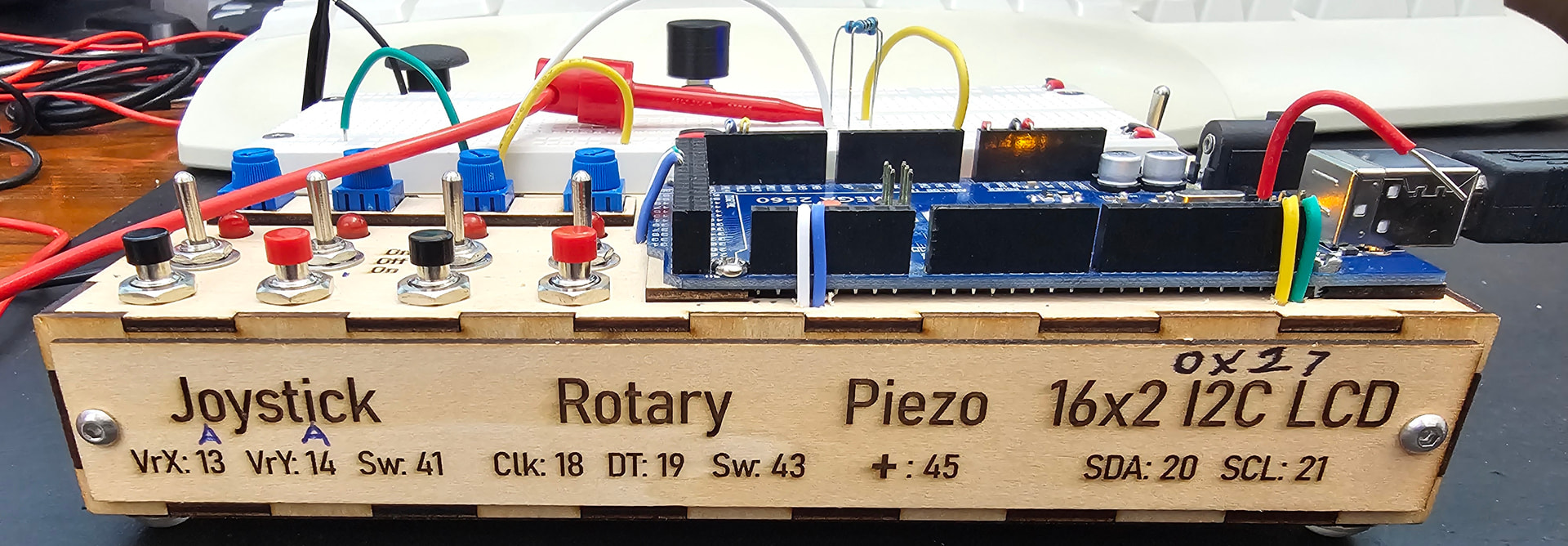
This is the prototyping box I built to make it easy to experiment with:
The divider should supply half the reference voltage to the sensor.
When you had default Aref (5volt), the divider, with two equal resistors, made 2.5volt.
If you switch to 2V56, then the divider must supply 2V56 / 2 = 1.28volt.
Mid-voltage is needed so the AC wave has room to swing both ways, to ground and Aref.
This mid-voltage is not critical. Changing the 10k resistor to ground to 3k3 will give 3k3 / (10k + 3k3) * 5volt = 1.24volt. Close enough.
Leo..