I thought that the Nano was more or less obsolete, with only clones available, but it does still show as for sale on the Arduino site. However, the documentation on the site says:
"I2C: A4 (SDA) and A5 (SCL). Support I2C (TWI) communication using the Wire library (documentation on the Wiring website)."
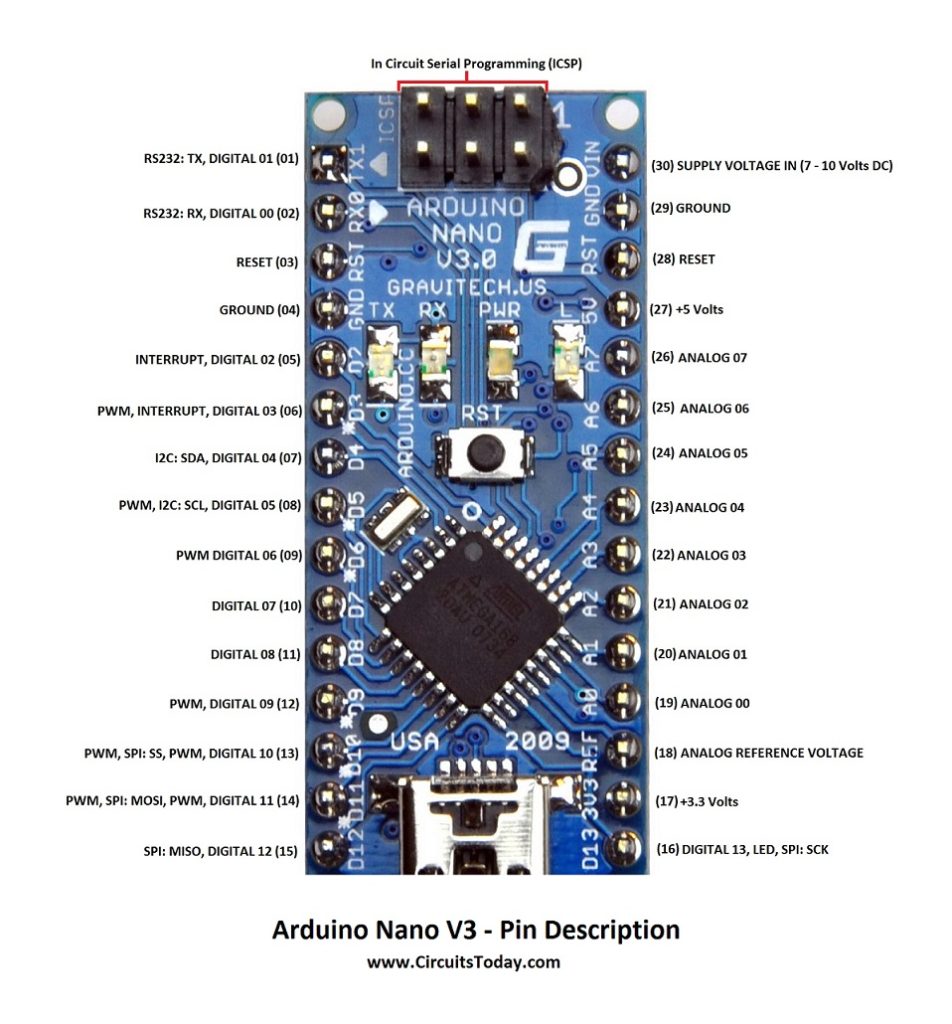
And the pinout diagram doesn't show SDA and SCL at all.
I finally found ONE website (not official) that said that SDA and ACL were not on analog pins, but on digital ones. Fixed my problem.
THANKS A LOT, Arduino! Would someone PLEASE fix the docs so others don't
waste as much time as I did?
On the Nano with an atmega328 (NOT the newer Nano Every and Nano 33 series), pin A4 is SDA and pin A5 is SCL. Same as on an UNO, or any other board based on the atmega328. Analog pins A0 through A5 can be used as either analog inputs, or digital input/output. Analog pins A6 and A7 are analog input ONLY.
< edit > Just checked, the Nano Every and the Nano 33 boards do have the I2C pins in the same location.
I think that documentation is absolutely correct,
it does not mention that analog is (apart from pins A6 and A7) an additional feature of a pin,
but that is not really part of the I2C documentation.
Maybe you can invoke a (much slower) software I2C emulation on pins D4 and D5,
that does not work on the real hardware I2C pins A4 and A5,
but the hardware I2C only works on pins A4 and A5 on a 328p,
and also on the 168 that is shown in your picture.
I was looking at it, comparing pinouts, circuit boards, and everything, even tracking the pcb traces in the photo. Whandall and johnwasser and jremington are 100% right.
This is the page with the picture at circuitsonline: https://www.circuitstoday.com/arduino-nano-tutorial-pinout-schematics.
The label on that picture with SDA and SCL is wrong, and if you scroll down, then they write: " I2C Pins 23, 24 as A4 and A5".
So they know the right pins.
Well there could be lots of other things wrong with your project.
Have you got pull up resistors on the I2C lines?
Is your I2C device actually working?
Are you feeding it the right date to the device to make it work?
Have you checked that the I2C signals are actually on the output pins with an oscilloscope or logic probe?
@LarryB your post has been moved. The installation and trouble shooting section is not for your project. Your post is clearly about your project.
Look, I didn't ask where SDA/SCL were - I asked why the docs all said it was in the wrong place. Perhaps there are variants between models, or between European/American/Asian versions. I do know that A4/A5 doesn't work for the clones I'm using, and D4/D5 does. And I'm using the standard Adafruit library.
I've written SCADA programs for nuclear power plants, smelters, rolling mills, White Sands, and a space shuttle emulator for NASA. So I'm not some newbie.
BTW, the shuttle was the most fun. I got to sit in a mock up cockpit and test my software :-).
I see no need to try and convince all you "experts" of anything, so I'm dropping this topic now. Have fun.
Good to know, but those would probably be called semifunctional counterfeits, not clones, and are best avoided as they may have other, more serious defects. For example: what about the normal alternative functions of the PD4 and PD5 pins?
Please post a link to where you got those, so that others can be warned.
On Amazon or Ebay. Been using them from various vendors for years. No problems other than the one pinout difference, but I've hardly used the analog input pins (other than as digital), or the imitation analog outputs. Here's one vendor I've used on Ebay: The vendor I've used on Amazon appears to have folded his tent. I've also bought Uno and Mega boards that way. I'm a retiree and have to watch my spending. No problems so far. P.S. It's interesting that the Adafruit servo software has no problems with it. Either it's a known and common difference, or they do a search to find the pins which would indicate that variant locations are not unknown.


