SDA and SCL switched.... no comm

I'm working on a small i2c project involving a pro mini and LCD 16x2.
When I first tried to turn on the project the controller had power on it for a few minutes with SDA and SCL switched around (I had accidentally placed the wires wrong)

Will this damage the controller? I switched the wires so that they are now correct but still no communication. I placed my O-scope on the SCL and it didn't show any clock rate.

Any suggestions?

Yes, the wire.h library is included and I'm 98.793% sure my circuit is correct.

Exchanging SDA and SCL will cause no harm at all.

You want to install the HD44780 library using the library manager in the IDE and use the examples provided with that library to get your system working.


Do you know how to adjust the contrast control?

Which Adruino? Which pins for SDA and SCL? The SDA and SCL pins are not A4 and A5 on a Mega.

Thanks paul,
I do also have the LCD i2c library included.
is that the library you suggested?

This is my current code. It is rough draft.

#include <Wire.h>
#include <LiquidCrystal_I2C.h>
LiquidCrystal_I2C lcd(0x27, 2, 1, 0, 4, 5, 6, 7, 3, POSITIVE);

//PINS
int X = A0;
int Y = A1;
byte HOLD = 4;
byte Press = 5;

//VARIABLES
int XVAL;
int YVAL;
int Xx;
int Yy;
int XvalLeft;
int XvalRight;
int YvalLeft;
int YvalRight;
int XvalLeftA;
int XvalRightA;
int YvalLeftA;
int YvalRightA;
int XLMAXVAL;
int XRMAXVAL;
int YLMAXVAL;
int YRMAXVAL;

int count;

void setup() {

  pinMode(HOLD, INPUT);
  pinMode(Press, INPUT);
  count = 1;
  lcd.begin(16, 2);
  lcd.setCursor(0, 0);
  lcd.print("    7EVEN6IX    ");
  lcd.setCursor(0, 1);
  lcd.print("  BRUUUTHERRRR  ");
  delay(5000);
}

void loop() {
  XVAL = analogRead(X);
  YVAL = analogRead(Y);
  Xx = map(XVAL, 0, 1023, 1, 16);
  Yy = map(YVAL, 0, 1023, 1, 16);
  XvalLeft = map(XVAL, 0, 512, 100, 0);
  XvalRight = map(XVAL, 512, 1023, 0, 100);
  YvalLeft = map(YVAL, 0, 512, 100, 0);
  YvalRight = map(YVAL, 512, 1023, 0, 100);

  if (digitalRead, HOLD == HIGH) {
    lcd.clear();
    lcd.setCursor(0, 0);
    lcd.print("X");
    lcd.setCursor(0, 1);
    lcd.print("Y");
    BarGraph();
  }

  if (digitalRead, HOLD == LOW) {
    lcd.clear();
    ScrollMax();
  }
}

void BarGraph() {
  if (XvalLeftA > XvalLeft) {
    XLMAXVAL = XvalLeftA;
  }
  if (XvalRightA > XvalRight) {
    XRMAXVAL = XvalRightA;
  }
  if (YvalLeftA > YvalLeft) {
    YLMAXVAL = YvalLeftA;
  }
  if (YvalRightA > YvalRight) {
    YRMAXVAL = YvalRightA;
  }
  XVAL = analogRead(X);
  YVAL = analogRead(Y);
  Xx = map(XVAL, 0, 1023, 1, 16);
  Yy = map(YVAL, 0, 1023, 1, 16);
  XvalLeft = map(XVAL, 0, 512, 100, 0);
  XvalRight = map(XVAL, 512, 1023, 0, 100);
  YvalLeft = map(YVAL, 0, 512, 100, 0);
  YvalRight = map(YVAL, 512, 1023, 0, 100);

  XvalLeftA = XvalLeft;
  XvalRightA = XvalRight;
  YvalLeftA = YvalLeft;
  YvalRightA = YvalRight;

  lcd.setCursor(Xx, 0);
  lcd.print("7");
  lcd.setCursor(Yy, 1);
  lcd.print("6");
}

void ScrollMax() {

  if (digitalRead, Press == HIGH); {
    delay(25);
    lcd.clear();
    count++;
    if (count = 4); {
      count = 1;
    }
  }
  switch (count) {
    case 1:
      lcd.setCursor(0, 0);
      lcd.print("Max Readings");
      break;
    case 2:
      lcd.setCursor(0, 0);
      lcd.print("Left       Right");
      lcd.setCursor(0, 1);
      lcd.print(XLMAXVAL);
      lcd.setCursor(9, 1);
      lcd.print(XRMAXVAL);
      break;
    case 3:
      lcd.setCursor(0, 0);
      lcd.print("Accel      Decel");
      lcd.setCursor(0, 1);
      lcd.print(YLMAXVAL);
      lcd.setCursor(9, 1);
      lcd.print(YRMAXVAL);
      break;
  }
}
groundFungus:
Which Adruino? Which pins for SDA and SCL? The SDA and SCL pins are not A4 and A5 on a Mega.

the Arduino proMini

No, that is not the library.

I am with Paul__B on the use of the hd44780 library.

For an I2C LCD display to work, the I2C address and the I2C backpack to LCD pin mapping must be correct. If the library default settings for either or both are not correct the LCD will not work. You can try to figure out the right pin mapping and use an I2C scanner to find the address, but if you install and use the hd44780 library that is done automatically by the library.

Install the hd44780 library. The hd44780 library is the best available for I2C LCDs. The library is available in the Library Manager. Go to Library Manager (in the IDE, Sketch, Include Libraries, Manage Libraries) and in the Topics dropdown choose Display and in the Filter your search box enter hd44780. Select and install the hd44780 library by Bill Perry.

The class that you want to use is the hd44780_I2Cexp class. There are examples to show how to use the library. The nice thing about the hd44780 library is that it will autodetect the I2C address and the I2C backpack to LCD pin mapping.

In the examples, there is a diagnostic sketch that will help us to help you if you still have trouble with the display. Run the diagnostic sketch and post the results.

I'll give it a try.

Any thoughts to why I had no SCL signal on the A5 pin?
like I mentioned earlier.... the O-scope didn't show any type of square wave. It stayed high.
or will this issue be corrected with the new library?

Any thoughts to why I had no SCL signal on the A5 pin?

Well you should see something if you have the right pin and it has not previously been damaged. Swapping them over will cause no harm. You do need a pull up resistor on each line of 4K7 but that would not stop you seeing a signal.

Is it a dual trace scope? If so trigger on the clock and look at the data.

Any thoughts to why I had no SCL signal on the A5 pin?

No, but if it happens with the hd44780 library run the diagnostic sketch and post the results. The results may give us clues to trace the problem.

The author of the hd44780 library (bperrybap) is often on the forum and is very helpful with problems with use of his library. The same cannot be said of authors of the other LCD libraries.

Grumpy_Mike:
Well you should see something if you have the right pin and it has not previously been damaged. Swapping them over will cause no harm. You do need a pull up resistor on each line of 4K7 but that would not stop you seeing a signal.

Is it a dual trace scope? If so trigger on the clock and look at the data.

yes it has dual trace.... I'm using a 5.1k resistors, I'm all out of 4.7k.

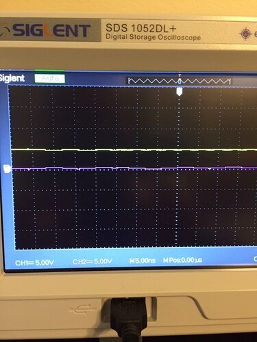
I checked the SDA and SCL again. I looks to have some noise that is consistent with "normal operation"
however, the SDA is around 0 and SCL is around 5 on the voltage scale.

There is no definite 5 to 0 jumps on either line showing that 5v is being pulled low as it should be.

perhaps I have a short to ground on the SDA??

pic of Oscope. Yellow is clock purple is data

perhaps I have a short to ground on the SDA??

Well given that you said:-

.... the O-scope didn't show any type of square wave. It stayed high.

That might be a short to the supply.

Load a blink sketch and see if that pin can toggle up and down.

By the way I can't see anything on either of those lines that looks like a clock.

When the bus is idle (like most of the time, as you won't be sending data) the lines are kept high. So that explains why you don't see anything.

No need to mess around with a scope. Run an I2C scanner. That'll keep the bus pretty busy, and the moment it returns the address of your display you also know you have the wiring correct. Note that some displays are at 0x27, others at 0x3F. Yours may have yet another address, the I2C scanner will tell.

Or install the hd44780 library and run the diagnostic sketch. Post the results. The hd44780 diagnostic will have more information than running the scanner sketch.

Just for everybody who had input on this topic.
I used another proMini and now it works.
I found two issues in my hardware.
A) I was using a 3.3 board and put 5 to the vcc
B) Solder issue on the data pin on the backpack

Thank you.

LandonW:
B) Solder issue on the data pin on the backpack

That will do it! :astonished:

I had attempted to pull out the header-pins with my iron and pliers. I had to turn my heat to max. I think the eyelet got pulled out and I didn't notice when I soldered a wire into that hole.