I'm working on a thermostat project that switches a heater on/off by sending the same 38kHz NEC signal from ~8m (26ft) away using the IRremote library (IrSender.SendNEC). It works fine after powering up for some tens of minutes, then the IR transmission fails from time to time.
I just connect this directly to an Arduino output pin since the maximum current is 38mA
Power source: I also tried two methods
A USB power bank which has a large capacity. However when using the IR333 LED the power bank stopped sending power. My speculation is that the total current is too high during IR transmission and when it falls back to idle the power bank thinks whatever charging task is completed and stopped supplying power. This does not happen with the LED with smaller current.
4-AA battery pack with 4 1.2V rechargeable batteries. This dies out soon though.
Other than the IR transmitting logic, I have an I2C OLED screen, two buttons, an active buzzer and a red LED to indicate the thermostat status and adjust the settings. I don't use interrupts for any of them (but the I2C screen might be using one?) and I calls SendNEC in its own timeframe separated from other update logic.
Using any combination of the IR LED and power source, the thermostat works fine at the first ten minutes or so. Without touching the thermostat (and messing up the IR angle), sending the remote signal only works intermittently afterwards. I still got normal indications that the thermostat thinks it has sent the signal, but the heater sometimes just does not receive the signal.
Any suggestions on potential causes/other debug methods would be much appreciated, thanks!
Edit #1
Schematics (directly connecting LED to Arduino pin):
Per suggestion of #11 I reduced the distance from the LED to the heater by half and now it works every time. It seems that now the problem is the IR LED (from the sensor kit) is not bright enough.
I'll test the superbright LED (IR333) with a more stable power source from far away to see if that can improve. Thanks everyone for your reply!
Edit #3
I ended up getting it work consistently by following #16:
Can you arrange to confirm that a) the IR signal is being sent after the 10 minutes? And/or b) that the IR signal is being received?
This should help to identify the transmitting or receiving portion is causing the problem.
I'm not sure what would be a good method to confirm a). I tried to use a red LED instead of IR led but the sending period is too short and hardly visible. I used the buzzer to indicate that a signal is being sent, but sometimes I hear the buzzer while the heater is not switched.
As for b), both my thermostat and the heater is in a fixed place in my room. There are cases where a signal is not received by the heater but minutes later it worked, so my guess is that the receiving side is working.
I ended up buying a pokit meter. I'm thinking about making the buzzer buzz several seconds before sending the IR signal so that I can have time to start precise measure mode. I'll update the result once I get it.
One method of testing for IR transmission is viewing the transmitting LED with a digital camera, e.g. mobile phone.
I forgot to offer that option earlier, oops.
Another one I used for many years to test TV remote controls is an IR LED into the BNC socket of a scope. Make sure the leads are very short (no hum/RF pickup) and flip if polarity is wrong.
Test with IR remote at about 20cm distance.
I managed to fit a 5mm IR LED into a BNC plug, with only a small part of the dome sticking out.
Leo..
How could I miss that! That was the reason I bought the superbright LEDs (IR333) because I thought the LED from the sensor kit is not bright enough. I tried to reduce the distance by half and now it works constantly.
My problem now becomes how to make either LEDs brighter to work at the intended distance. I'm editing my main post for that. Thanks!
Thanks, I tried to use my phone camera and it indeed shows the LED flash albeit very quick. However I cannot find an angle to record the flash clearly while not blocking the path of light to the heater.
Right now the problem seems to be the LED is not bright enough for it to work every time.
Use two LEDs in series. Or two (or more) sets of two, each with their own CL resistor.
Each LED drops about 1.5volt when pulsed with high current, so calculate your CL resistor accordingly.
I wouldn't use three LEDs in series, or pulse more than 200mA with a simple CL resistor.
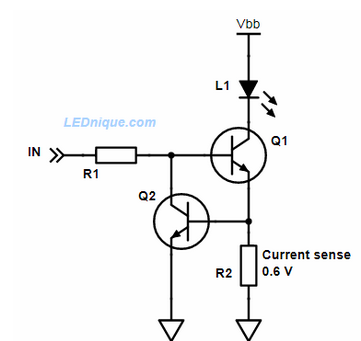
What value is the 2N2222 base resistor (should be 220 ohm).
Leo..
Assuming that you have only a 5V supply; can you confirm? Then two LEDs in series (needing ~2 x 1.5V at 100mA, 2 x ~2.3V for 0.5A) gives limited headroom for your series current limiting resistor, or too close to none for 0.5A according to the data sheet. A small variation in the 5V supply may have an adverse affect on the LED current.
You may want to consider a constant current drive:
Ref.
As Wawa said, you can put LEDs and their drive in parallel - more current of course. Two LEDs in series with ~300mA current may be less strain on your power supply.
If you have a greater voltage power supply, than your 5V, this circuit will allow multiple LEDs in series. If, say, a 12V supply then you could have many series.
Please consider using substantial power supply decoupling, with those 0.5A pulses the power supply may struggle. Your first posting alluded to this.
My quick and rough calculation gives a 1000uF cap dipping by 6mV during on a single IR pulse transmission, due to the 0.5A drain.
Thank you for the base resistor value! I tried to use two LEDs in series previously but it didn't work. Apparently my calculations are way off and I used a much larger base resistor (1k ohm).
Now using the 220 ohm base resistor it seems to be working fine. The power source I used is the 4-AA battery pack at 4.8V, since the power bank automatically turns off after an IR transmission. I'll leave it running for a day to see if the problem is indeed solved.
Thanks for the detailed explanation and calculation! I have absolutely no idea how a constant-current driver works as I was struggling in my analog circuit courses in college. Calculating a circuit with only one NPN is the hardest math I was confident to do and I did it wrong .
That being said, unfortunately I don't have access to either 12V supply or 1000uF capacitors today (all I have is from this breadboard kit with capacitors up to 100uF). Plus I'm still waiting for the multimeter to arrive.
The power issue about my power bank is not too much current, since the power bank should be able to supply at least 5V2A for charging phones. The issue is that after the current fell from a high peak, the smart power bank thinks it has completed the job of charging a device and automatically shuts down the USB port.
I ended up putting two LEDs in series with a 220 ohm base resistor as Wawa mentioned in #16 and switched to the 4-AA 4.8V battery pack. Hopefully the <5V would never break the LEDs/NPN while still providing enough power for IR to reach the heater.
Sorry, but forget the constant current stuff for IR sending, it is overkill and reduces the voltage available for your diodes.
In the diodes datasheet you see 1.5 volt for the allowed 100 mA.
So you have around 1.8 volt left at the resistor. With U = R * I you get R = U / I and 18 Ohms (instead of your 220 Ohm).
Now you know how to boost your transmission distance
And forget about the 2N2222, the ARDUINO can drive up to 25 mA, so using a 100 Ohm resistor is always save and increases the sending power by 2 (compared with your 220 Ohm) or the sending distance by sqrt(2).