Serial Issue with I2C Sensor

I am working to build a stabilizer for a remote controlled airplane. The project utilizes a Mega reading serial from a Spektrum satellite receiver, Adafruit's PWM Servo I2C Interface shield, along with Adafruit's BNO055 IMU.

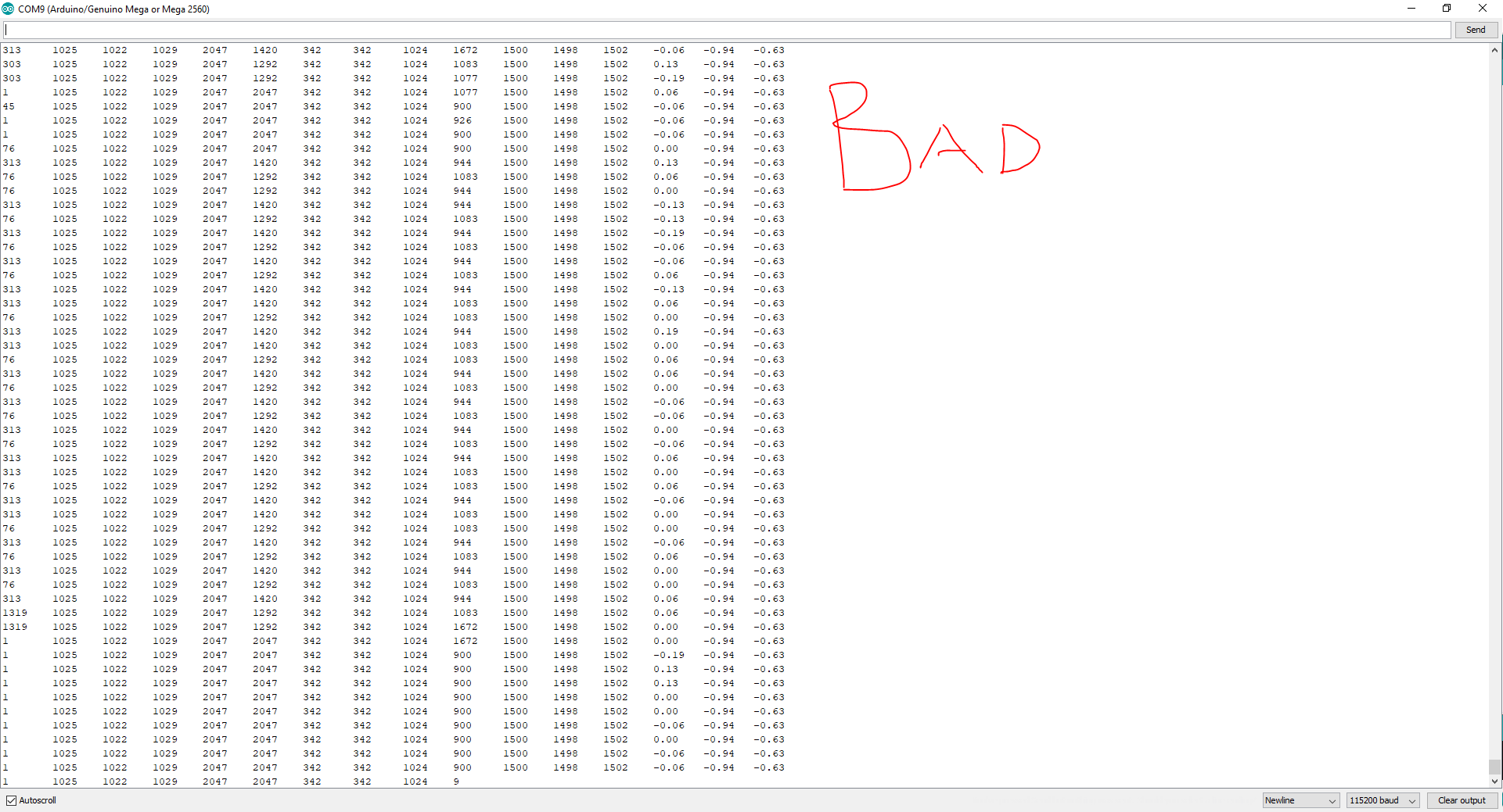
The project works just fine when I am only reading Spektrum serial and driving servos on the PWM/I2C shield. When I add in the BNO055 IMU the serial data becomes erratic, yet the orientation data appears to be smooth and correct. Also, errors appear when power is applied to the IMU even when the code is commented out.

Does this appear to be a hardware issue or is there a problem with the way I have written the code?

The code below is currently commented out i a way that works as described above. To "break it" and start reading the IMU remove the /* */ tags in void setup() and void().

SpektrumSattelite library: GitHub - Quarduino/SpektrumSatellite: Rx receiver library for Arduino DUE and the Spektrum DSMX Satellite receiver. Probably works with other Arduinos with some modifications.
Adafruit PWM/I2C Shield: Overview | Adafruit 16-channel PWM/Servo Shield | Adafruit Learning System
Adafruit BNO055 IMU: Overview | Adafruit BNO055 Absolute Orientation Sensor | Adafruit Learning System

/*  
    -- Radio Configuration --
 DX8 G2
 11ms DSMX
 +-150% Travel 
 
 -- RX Connections (MEGA 2650) --
 Connect Orange to 3.3V
 Connect Black  to GND
 Connect Grey   to Digital 15 - RX3

 Min Command 0     = -150% Both Gimbals Bottom Right
 Mid Command 1024  =    0% Both Gimbals Centered
 Max Command 2048  = +150% Both Gimbals Upper Left 

   -- BNO055 Connections (MEGA 2650) --
   
   SCL to SCL MEGA
   SDA to SDA MEGA
   Vin to 5.0V DC
   GROUND to common ground
*/

//Reading Spektrum Sattelite
  #include <SpektrumSattelite.h>
  SpektrumSattelite rx;

//Driving Servos Via I2C Shield
  #include <Wire.h>
  #include <Adafruit_PWMServoDriver.h>
  Adafruit_PWMServoDriver pwm = Adafruit_PWMServoDriver();

//Reading IMU
 //#include <Wire.h> Already required for I2C Shield
 #include <Adafruit_Sensor.h>
 #include <Adafruit_BNO055.h>
 #include <utility/imumaths.h>
 #define BNO055_SAMPLERATE_DELAY_MS (100) 
 Adafruit_BNO055 bno = Adafruit_BNO055();

//Initialize Input/Output Varibles
  int CH1 = 1000;
  int Thro = 0;
  int CH2 = 1000;
  int Aile = 0;
  int CH3 = 1000;
  int Elev = 0;
  int CH4 = 1000;
  int Rudd = 0;
  int Gear = 0;
  float YAWRATE = 0;
  float ROLL = 0;
  float PITCH = 0;

void setup()
{
  Serial.begin(115200);
  Serial3.begin(115200); //SpektrumSattelite uses Serial3 for input 

  //Initialise BNO055 Sensor 
  /*if(!bno.begin())
  {
     //There was a problem detecting the BNO055 ... check your connections 
    Serial.print("Ooops, no BNO055 detected ... Check your wiring or I2C ADDR!");
    while(1);
  }
  
  bno.setExtCrystalUse(true);
  */

  //Initialise PWM/I2C Shield
  pwm.begin();
  pwm.setOscillatorFrequency(27000000);  // The int.osc. is closer to 27MHz
  pwm.setPWMFreq(50);  // 
  Wire.setClock(400000);
}

void loop(){

  //Read BNO055 Data
  /*imu::Vector<3> euler = bno.getVector(Adafruit_BNO055::VECTOR_EULER);
  imu::Vector<3>  gyro = bno.getVector(Adafruit_BNO055::VECTOR_GYROSCOPE);
  
  YAWRATE = gyro.z()*180/3.14159;
  ROLL = euler.z();
  PITCH = euler.y(); 
  */
  
  rx.getFrame();         //READ CH1-CH9 Spektrum 
  ErrorChk();            //Report Current Varibles

  Thro = rx.getThro();
  Aile = rx.getAile();
  Elev = rx.getElev();
  Rudd = rx.getRudd();
  Gear = rx.getGear();

  CH1 = map(Thro,0,2048,900,2100); // THROTTLE - map input to pwm freq
  pwm.writeMicroseconds(0,CH1);    // Write PWM 

  CH2 = map(Aile,0,2048,900,2100); // AILERON
  pwm.writeMicroseconds(1,CH2);   

  CH3 = map(Elev,0,2048,900,2100); // ELEVATOR 
  pwm.writeMicroseconds(2,CH3);   
 
  CH4 = map(Rudd,0,2048,900,2100); // RUDDER 
  pwm.writeMicroseconds(3,CH4);   

}


void ErrorChk(){ 
  Serial.print(rx.getThro());
  Serial.print("\t");
  Serial.print(rx.getAile());
  Serial.print("\t");
  Serial.print(rx.getElev());
  Serial.print("\t");
  Serial.print(rx.getRudd());
  Serial.print("\t");
  Serial.print(rx.getGear());
  Serial.print("\t");
  Serial.print(rx.getPitc());
  Serial.print("\t");
  Serial.print(rx.getAux2());
  Serial.print("\t");
  Serial.print(rx.getAux3());
  Serial.print("\t");
  Serial.print(rx.getAux4());
  Serial.print("\t");
  Serial.print(CH1);
  Serial.print("\t");
  Serial.print(CH2);
  Serial.print("\t");
  Serial.print(CH3);
  Serial.print("\t");
  Serial.print(CH4);
  Serial.print("\t");
  Serial.print(YAWRATE);
  Serial.print("\t");
  Serial.print(ROLL);
  Serial.print("\t");
  Serial.print(PITCH);
  Serial.print('\n');
 }

OP image:

errors appear when power is applied to the IMU even when the code is commented out

Shouldn't you stop right there, and look at hardware issues first? In the image, I see no 3.3V-5V level translation. It's hard to troubleshoot any more visually because I'm not familiar with that shield.

I haven't pursued hardware very close, because if I do every element individually they each work. Serial read works on its own and and the IMU works on its own with the same circuit. Only if I try to do both at the simultaneously do I get the issue.

What is 3.3V-5V level translation?

Please explain what these two statements mean, and give examples:

the serial data becomes erratic

errors appear when power is applied to the IMU even when the code is commented out

"Level translation" is an interface that is required to connect 5V devices with 3.3V devices. The BNO055 is a 3.3V device, but has built in level translation so that you can safely connect it to a 5V Arduino.

I have attached a screen shot of each "good" and "bad" data streams. The good data is vary constant (columns 1-9) and predictable as I change the controller position. The bad/erratic data all comes through; though, is constantly changing and each channel appears to affect multiple outputs rather than its single channel.

With more testing I am wrong in my comment of having the hardware hooked up but the code commented out being an issue. Only when I try to read the IMU in code do I get the bad data issue.

Thank you for you description of a level translation. Since the IMU has this built in it sounds as though I do not need to implement one?

Sorry, I don't have any idea what those data streams represent, or why one should be "good" and the other "bad".

Please tell us what we are looking at, what you expected to see, what went wrong, and explain the basis for your value judgement.

The "How to use this forum" post has helpful hints for explaining the problems you are having.

The BNO055 is a 3.3V device, but has built in level translation so that you can safely connect it to a 5V Arduino..

Finally, it is ALWAYS best to practice with each sensor individually, so you know exactly what it does and how to interpret the results. Then add the bits together.

Confused.
Do you power the IMU from the servo supply pin? (power from the screw terminal)

Shouldn't you connect IMU SDA/SCL/power directly to the Mega instead of running it over that servo board.
SDA = pin20
SCL = pin21
5volt (end of the double row, near pin21) to V-in of the IMU
ground (end of the double row, near pin15).
Leo..

Edit: Adafruit boards have AFAIK always I2C level translation buildin.

+1 what Wawa said above.

Also, if the BNO055 is anywhere near motors or servos, don't expect it to work properly. Stray magnetic fields are death to a magnetometer/compass.

jremington:

Thank you for your suggestions.

Columns 1-9 (starting from the left) are the streams from the RC receiver serial and should be 0-2048. These values is where my issue lays.

While the serial data read is working standalone the values (1-9) are consistent over time with a constant input on the RC transmitter. When I bring the serial read and the IMU read together those values become very noisy. Interestingly the IMU data the 3 most right columns are very consistent and appear to be correct and smooth as I move the sensor.

I am able to test each feature/sensor individually with success, and I am reaching out for assistance after having failed in assembling each component of this project in to one operation.

No servos are motors are implemented right now so I don't expect any major interference - but what do I know? :slight_smile:

Wawa:

In the attached photo I am powering the IMU from the 5V servo rail on the middle of the shield, with the SCL/SDA going straight to the MEGA. The jumpers just happen to be going through the pins raised on the shield.

I suggest to remove the servo shield and all the program calls that instance the servo library, set pwm, etc.

Connect the radio and the BNO055 directly to the mega and test that combination.

Elijahl:
In the attached photo I am powering the IMU from the 5V servo rail on the middle of the shield, with the SCL/SDA going straight to the MEGA. The jumpers just happen to be going through the pins raised on the shield.

Don't.
Servo power (middle pins) comes from the screw connector, and has nothing to do with the Mega itself.
Leo..

This morning I incrementally tried your suggestions one at a time. I removed the PMW servo shield and associated program calls. Simultaneously I rewired the IMU to power directly off the MEGA hooked up the SCL/SDA straight to the MEGA as well.

In addition I implemented pull up and series resistors incrementally per a suggestion on a similar forum. I2C interference by serial communication

Unfortunately with no improvement. I'm concerned there is a a timing issue and the MEGA cant cope with the simultaneous signals. I don't have access to a logic analyzer is there another way I could test this theory?

Please post the revised code and a hand drawn figure showing the revised wiring diagram.

The Arduino should not have any trouble at all sorting the two serial data streams. I've used the BNO055 with a GPS module, LCD display and motor drivers for long periods of time as the navigation system for an autonomous boat, and have never seen the type of errors you are encountering.

That said, the Arduino implementation of I2C is quite limited in ability to handle error conditions. You might try using the more advanced I2Cdev, attached. There are some examples of its use for the MPU-9250 sensor in the folder.

I2Cdev.zip (42.2 KB)

I will look into the I2Cdev. Please see the updated code and wiring diagram and let me know if there are any glaring issues.

Thanks for sharing!

//Reading Spektrum Sattelite
  #include <SpektrumSattelite.h>
  SpektrumSattelite rx;

//Reading IMU
  #include <Wire.h> Already required for I2C Shield
  #include <Adafruit_Sensor.h>
  #include <Adafruit_BNO055.h>
  #include <utility/imumaths.h>
  #define BNO055_SAMPLERATE_DELAY_MS (100) 
  Adafruit_BNO055 bno = Adafruit_BNO055();

//Initialize Input/Output Varibles
  int CH1 = 1000;
  int Thro = 0;
  int CH2 = 1000;
  int Aile = 0;
  int CH3 = 1000;
  int Elev = 0;
  int CH4 = 1000;
  int Rudd = 0;
  int Gear = 0;
  float YAWRATE = 0;
  float ROLL = 0;
  float PITCH = 0;

void setup()
{
  Serial.begin(115200);
  Serial3.begin(115200); //SpektrumSattelite uses Serial3 for input 

  //Initialise BNO055 Sensor 
  if(!bno.begin())
  {
     //There was a problem detecting the BNO055 ... check your connections 
    Serial.print("Ooops, no BNO055 detected ... Check your wiring or I2C ADDR!");
    while(1);
  }
  
  bno.setExtCrystalUse(true); 
}

void loop(){

  //Read BNO055 Data
  imu::Vector<3> euler = bno.getVector(Adafruit_BNO055::VECTOR_EULER);
  imu::Vector<3>  gyro = bno.getVector(Adafruit_BNO055::VECTOR_GYROSCOPE);
  
  YAWRATE = gyro.z()*180/3.14159;
  ROLL = euler.z();
  PITCH = euler.y(); 
  
  rx.getFrame();         //READ CH1-CH9 Spektrum 
  ErrorChk();            //Serial Print Current Varibles

  Thro = rx.getThro();
  Aile = rx.getAile();
  Elev = rx.getElev();
  Rudd = rx.getRudd();
  Gear = rx.getGear();

  CH1 = map(Thro,0,2048,900,2100); // THROTTLE 
  CH2 = map(Aile,0,2048,900,2100); // AILERON
  CH3 = map(Elev,0,2048,900,2100); // ELEVATOR 
  CH4 = map(Rudd,0,2048,900,2100); // RUDDER 

}


void ErrorChk(){ 
  Serial.print(rx.getThro());
  Serial.print("\t");
  Serial.print(rx.getAile());
  Serial.print("\t");
  Serial.print(rx.getElev());
  Serial.print("\t");
  Serial.print(rx.getRudd());
  Serial.print("\t");
  Serial.print(rx.getGear());
  Serial.print("\t");
  Serial.print(rx.getPitc());
  Serial.print("\t");
  Serial.print(rx.getAux2());
  Serial.print("\t");
  Serial.print(rx.getAux3());
  Serial.print("\t");
  Serial.print(rx.getAux4());
  Serial.print("\t");
  Serial.print(CH1);
  Serial.print("\t");
  Serial.print(CH2);
  Serial.print("\t");
  Serial.print(CH3);
  Serial.print("\t");
  Serial.print(CH4);
  Serial.print("\t");
  Serial.print(YAWRATE);
  Serial.print("\t");
  Serial.print(ROLL);
  Serial.print("\t");
  Serial.print(PITCH);
  Serial.print('\n');
 }

Wiring Diagram.pdf (337 KB)

Assuming that the symptoms from the latest circuit match those of the good and bad data posted earlier, I don't see anything wrong with what you have done.

I wonder if the data from the receiver really are "bad". It is very strange that some values would simply change by a certain amount, and not be complete nonsense (which you would expect if some sort of interference is at fault).

BTW did you notice this comment in the Spectrum library (.cpp file)? The Mega is "similar" to the Uno.

//To make it work on UNO or similar, change all shorts to ints and select the right serial

Good catch! I switched over to the ints in place of shorts but came to the same issue.

When I disconnect the IMU hardware but attempt to run its code the serial still goes haywire... Not till I comment out 100% of the IMU code does the serial restore to normal. :frowning:

That is really mysterious. It is very hard to imagine how hardware I2C and hardware serial could interfere with each other. Millions of people use both, all the time.

Nothing occurs to me except, out of desperation, to switch the receiver to another hardware serial port. If you can change the receiver Baud rate to a much lower value, try that too. Change the Arduino code to match.