Hi, I'm working with an Arduino with components such as an SN74LS138, two 6116 SRAMs, and an SN74LS373. When I run the program, the serial monitor should show two binary numbers based on the value I put in.
The problem is that the serial monitor shows the binary output as reversed than what's expected. So my value for the 1st SRAM could be 0x12 and it should display 00010010 on the serial monitor. Instead, it shows up as 01001000. How do I go to fix the order on how it displays?
<
/* Control pin definitions. /
#define PIN_INT 2
#define PIN_READ 25 / Connected to OE' on SRAMs. /
#define PIN_WRITE 27 / Connected to WE' SRAMs. /
#define PIN_ALE 29 / Connected to the 373 for address latching. /
#define PIN_M_IO 23 / Connected to the 138. Disabled = no chips selected. */
/* AD pin mapping. */
static uint8_t AD_PINS[ ] = {24, 28, 32, 36, 40, 44, 48, 52};
#define AD_PINS_SIZE (sizeof (AD_PINS) / sizeof (AD_PINS[0]))
/* ALE and M_IO signalre are active high. */
#define ALE_DISABLE() digitalWrite(PIN_ALE, LOW);
#define ALE_ENABLE() digitalWrite(PIN_ALE, HIGH);
#define M_IO_DISABLE() digitalWrite(PIN_M_IO, LOW);
#define M_IO_ENABLE() digitalWrite(PIN_M_IO, HIGH);
/* Both read and write signals are active low. */
#define WRITE_DISABLE() digitalWrite(PIN_WRITE, HIGH);
#define WRITE_ENABLE() digitalWrite(PIN_WRITE, LOW);
#define READ_DISABLE() digitalWrite(PIN_READ, HIGH);
#define READ_ENABLE() digitalWrite(PIN_READ, LOW);
void setup() {
pinMode(24, INPUT);
pinMode(28, INPUT);
pinMode(32, INPUT);
pinMode(36, INPUT);
pinMode(40, INPUT);
pinMode(44, INPUT);
pinMode(48, INPUT);
pinMode(52, INPUT);
pinMode(PIN_READ, OUTPUT);
pinMode(PIN_WRITE, OUTPUT);
pinMode(PIN_ALE, OUTPUT);
pinMode(PIN_M_IO, OUTPUT);
Serial.begin(9600);
// SRAM1
memWrite(0x30,0x12);
// SRAM2
memWrite(0x40,0x34);
memRead(0x30);
memRead(0x40);
}
void write_byte(uint8_t b)
{
int i;
for (i = 0; i < AD_PINS_SIZE; i++) {
pinMode(AD_PINS[i], OUTPUT);
}
for (i = 0; i < AD_PINS_SIZE; i++)
digitalWrite(AD_PINS[i], ((b >> i) & 1));
}
void read_byte(uint8_t b)
{
int I;
uint8_t d = 0b00000000;
for (i = 0; i < AD_PINS_SIZE; i++) {
pinMode(AD_PINS[i], INPUT);
d = digitalRead(AD_PINS[i]);
Serial.print(d);
}
Serial.print("\n");
}
void memWrite(uint8_t addr, uint8_t data)
{
READ_DISABLE();
M_IO_ENABLE();
/* First latch the address. */
address_latch(addr);
/* Tell the SRAM to take what's on the bus. */
WRITE_ENABLE();
/* Place the data onto the data bus. */
write_byte(data);
delay(1);
WRITE_DISABLE();
}
void memRead(uint8_t addr)
{
WRITE_DISABLE();
READ_ENABLE();
M_IO_ENABLE();
/* First latch the address. */
address_latch(addr);
read_byte(addr);
delay(1);
READ_DISABLE();
}
void address_latch(uint8_t addr)
{
digitalWrite(PIN_ALE, 1); // Prepare to latch an address
write_byte(addr); // Place addr on data bus
digitalWrite(PIN_ALE, 0); // Disable ALE so that subsequent writes to the bus are not latched
}
void loop() {
// put your main code here, to run repeatedly:
}
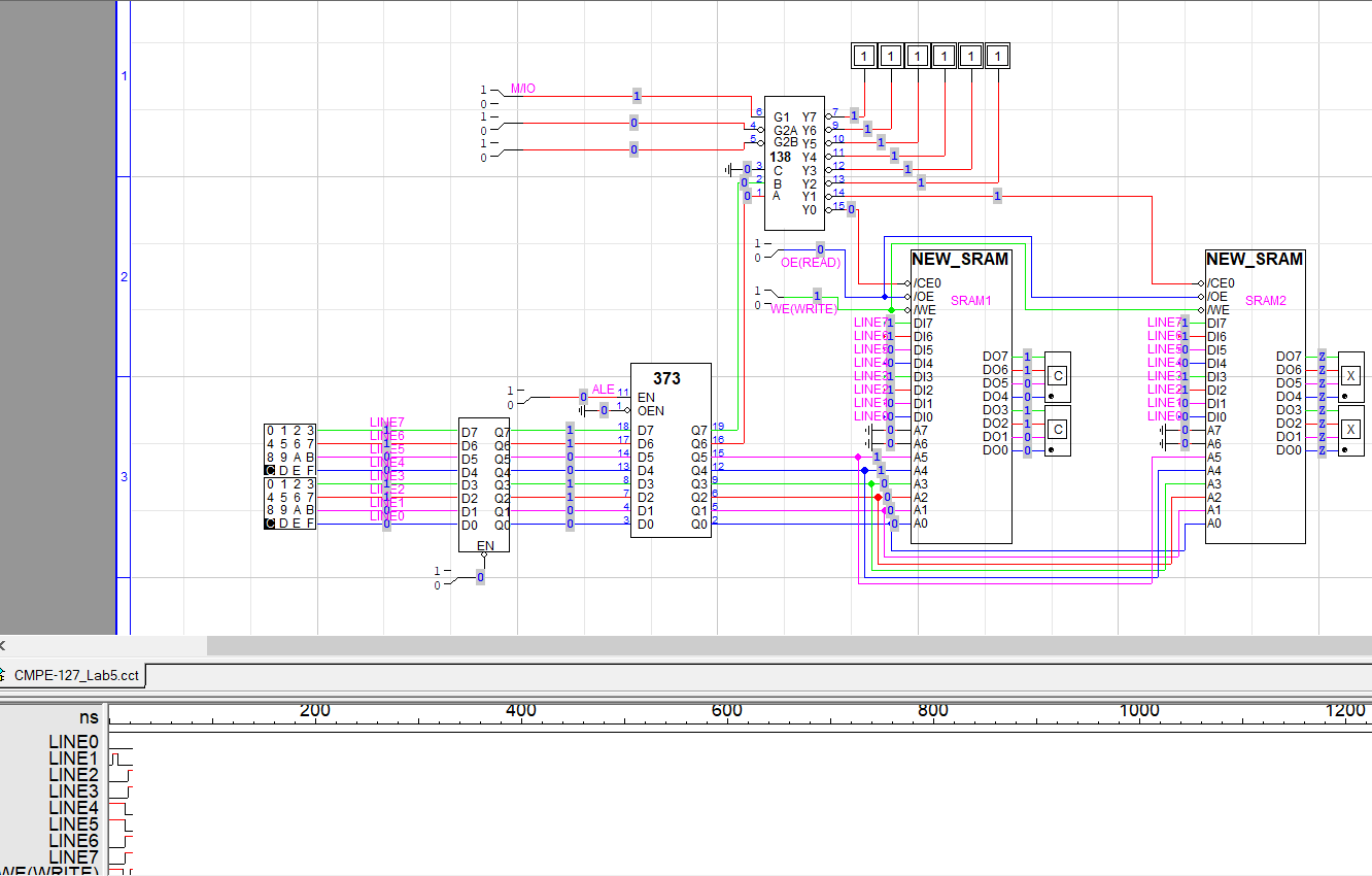
Circuit used