I'm attempting to send a signal via RS232 to trigger a laser firing. The only info I get is RS232 (9600-8-N-1), and the command syntax is "$FIRE 01CR". Only Tx and Rx are used, no other handshaking, CR is carriage return, 0Dh. Do I need to convert this into binary first? Or will the Mega2560 internally handle the signal and send as binary?
Below is my code, I'm using a button to induce a pin change from LOW->HIGH and detect the rising edge with attachInterrupt (I need the command sent only once, not repeatedly as long as the pin is HIGH).
The output on the Serial Monitor is "$FIRE 01" when I use Serial.println in place of Serial.write (as I understand it, Serial.write actually sends the signal to the serial pin).
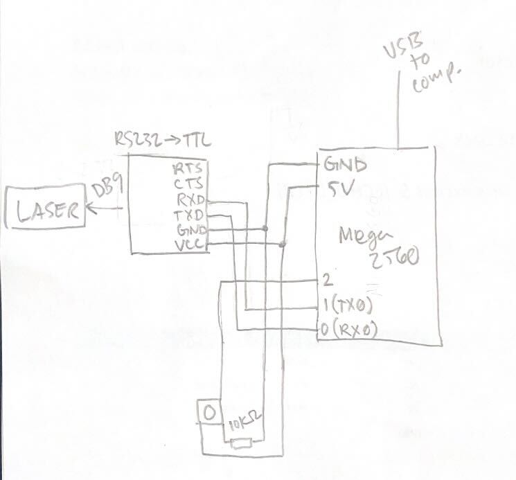
I'm using an RS232 to TTL converter between the laser and the arduino, with pin 0 (RX) connected to TX, and pin 1 (TX) connected to RX on the converter. When the button is pressed, I see both TX and RX flash, so I assume that means there was some kind of serial communication, however there's no response from the laser.
Very new to C++ and still confused on how Serial.print works/how to format the command for RS232 communication. Any help/explanation would be greatly appreciated. Below is m wiring diagram. Thanks!
Based on your labeling of your sketch, I suspect you need to swap TX and RX, at one end or the other, unless you have documentation indicating that TXD on the converter is an output.
I also think your button is wired wrong. Pullup has to be between 5V and the input pin. Though, there's also the built-in pullup resistor if you enable it.
99.99% of the time, using an interrupt for a button press is the wrong way to go, rising or falling. Code in loop detecting state change for the button, and debouncing it, will get you a lot further a lot more quickly.
I used the button here as a proxy for a pin state change trigger (I had been using is for testing other code and just kept it for this), is attachInterrupt still a poor choice for detecting the leading edge?
Since it's on a Nega, you could use one of the other hardware serial ports and leave rx0/tx0 for uploading and serial monitoring.
Both print and write send out data on the TX pin. It's hard to say what is appropriate in this circumstance, hence the desire to know what the laser thing is, or a link to where you learned anything about controlling it. Maybe it's a laser and is a little harder to make go.
"Note that I have removed the \n, as Serial.println sends CR (0x0D) followed by LF(0x0A)."
To clarify, for Serial.write, I should always include \r or \n?
After uploading the relevant sketch in MEGA, enter $FIRE 01 in the InputBox of the Serial Monitor (Fig-3) with Carriage return option and then click on the Send Button.
Yes, because a button will bounce many times, and putting debouncing in an interrupt routine is stand-on-your-head foolish.
You will find that without a lot of awkward work, the multiple interrupts emanating from bouncing contacts will result in multiple output messages, scrambling your attempt to turn the bus around at a consistent time.
I understand the bouncing issue for a physical contact trigger like a button, but for a non-button trigger (i.e. some other part of the code turns a trigger pin high), is attachinterrupt still a bad choice?
I Guess not, but then if the code sets an output, it can also set a flag variable. No need for the interrupt at all.
Not getting where you're coming from.
That will work better, no bouncing problem… but it raises the question - if some other part of the code can turn a trigger pin high, it could just do whatever the interrupt service routine was meant to do right there at the same time.
There is one advantage of interrupt over polling the flag. If using interrupt, the MCU is free from spending time to poll the flag; let the event notify its presence to the MCU through interrupt.
On the other hand, if the code would be triggering an interrupt through a pin change, it could just as easily call a function directly to do the work right there and then (no need for any interrupts or flags at all).
If the external event is asynchronous, there is no way for the main line program to decide the exact time of arrival of the event. In that case, either interrupt or flag has to be used to catch the event.
I was referring to the suggestion of triggering a pin change from code and catching the pin change with an interrupt from within the same sketch. If the sketch is changing a pin only to catch the pin's state change in an interrupt, it would be better to instead do the action right there in place of changing the pin's state.
I see now that @alto777 made the same suggestion as me.
I think my issue now is i'm not sure how to read the logic level change and send the command for laser operation only once (using the rising edge seemed like an accurate method for triggering a single fire command). So far, any code i've written for changing pin levels has been using digitalwrite() with delay(), but setting a delay time seemed less ideal than detecting the rising edge of a signal. I could be totally ignorant to some basic function for this.
Instead of discussing about right/wrong button trigger, why don't you just tx your laser directly from your code. Try all possible ways one after another (ascii, hex, print, write, /n, /r whatever) until that guy responds. It's not getting hurt. Then think about button.
Did I miss something??
Nope, you didnt miss anything, I just tried to do two things at once
Testing serial communication now.
The triggering/edge detection will be important in actual operation for precise triggering (the input will actually be from a different component not discussed here, which will be mediated via the arduino).
So waste of time until you have final trigger method. Anyway interrupt or loop, both are fine, one might be better than another in certain specific case... But don't do serial communication inside interrupt.
For now, kick that laser with all possible/impossible tx until it fires.