// https://forum.arduino.cc/t/servo-moving-on-its-own/1015174/21

//********************************************^************************************************
//  XXXXXXXXXXXXXXXXX.ino
//
//
//  Version   YY/MM/DD     Comments
//  =======   ========     ========================================================
//  1.00      22/07/22     Running code
//
//********************************************^************************************************

#include <Servo.h>
Servo servo1;

//********************************************^************************************************

#define LEDon                      HIGH
#define LEDoff                     LOW

#define PUSHED                     LOW
#define RELEASED                   HIGH

#define ENABLED                    true
#define DISABLED                   false

//********************************************^************************************************

const byte button1Pin            = 4;
const byte servo1Pin             = 10;
const byte heartbeatLED          = 13;

boolean timing2secFlag           = DISABLED;
boolean timing10secFlag          = DISABLED;

byte lastButton1State            = RELEASED;

//Timing stuff
unsigned long heartbeatMillis;
unsigned long switchMillis;
unsigned long start2secMillis;
unsigned long start10secMillis;
unsigned long currentMillis;


//********************************************^************************************************
void setup()
{
  Serial.begin(115200);

  pinMode(heartbeatLED , OUTPUT);

  //setting up servo to start in original position
  servo1.write(0);
  servo1.attach(servo1Pin);
  delay(100);

  servo1.detach();

  pinMode(button1Pin, INPUT_PULLUP);

} //END of    setup()


//********************************************^************************************************
void loop()
{
  //*********************************                              heartbeat TIMER
  //is it time to toggle the heartbeatLED ?
  if (millis() - heartbeatMillis >= 500ul)
  {
    //restart this TIMER
    heartbeatMillis = millis();

    //toggle the heartbeatLED
    digitalWrite(heartbeatLED, !digitalRead(heartbeatLED));
  }

  //*********************************                              switch TIMER
  //is it time to check the switches ?
  if (millis() - switchMillis >= 50ul)
  {
    //restart this TIMER
    switchMillis = millis();

    checkSwitches();
  }

  //*********************************                              servo 2 sec TIMER
  //if this 2 sec TIMER is enabled, has it expired ?
  if (timing2secFlag == ENABLED && millis() - start2secMillis >= 2000ul)
  {
    //we are finished with this TIMER
    timing2secFlag = DISABLED;

    servo1.write(0);
    Serial.println("Servo to 0");

    //enable the 10 sec TIMER
    timing10secFlag = ENABLED;

    //Start the 10 sec TIMER
    start10secMillis = millis();
  }

  //*********************************                              servo 10 sec TIMER
  //if this 10 sec TIMER is enabled, has it expired ?
  if (timing10secFlag == ENABLED && millis() - start10secMillis >= 10000ul)
  {
    servo1.detach();

    //we are finished with this TIMER
    timing10secFlag = DISABLED;
  }

} //END of   loop()


//********************************************^************************************************
void checkSwitches()
{
  byte button1State;

  //*********************************                                        button1Pin
  button1State = digitalRead(button1Pin);

  //was there a change in switch state
  if (lastButton1State != button1State)
  {
    //update to the new state
    lastButton1State = button1State;

    //if we are not timing, was the switch pushed ?
    if (timing2secFlag == DISABLED && timing10secFlag == DISABLED && button1State == PUSHED)
    {
      servo1.attach(servo1Pin);
      servo1.write(90);

      Serial.println("Servo to 90");

      //enable the 2 sec TIMER
      timing2secFlag = ENABLED;

      //reset the 2 sec TIMER
      start2secMillis = millis();
    }

  } //END of       button1Pin switch

} //END of   checkSwitches()

//********************************************^************************************************
Well
Is looking for a HIGH
So
if (button1State == LOW) {
Is looking for a LOW
Well this is wrong
Because the call to set it to zero only has 0.1 seconds to go back to zero before you disable the servo. Then that would mean it would freeze for ten seconds before zipping back to zero.
**do not detach the servo **
Hi, @mruiz02
Welcome to the forum.
Is there a reason why you keep attaching then detaching the servo?
Can I suggest you get rid of ALL the attach and detach statements and just have ONE attach statement in the setup of your code.
Tom.... ![]()
![]()
![]()
![]()
PS, In your code you have 4 attach and 2 detatch.
2 Likes
Button wired between 5V and input, no pulldown resistor is also a problem, won't work as expected. Better to wire it between ground and input, and use INPUT_PULLUP. this will then require that your code expect a low on that input when the button is pressed.
Fix this now, as with it the way you have it, you may think other recommendations aren't working when they actually are.
C
It would be if that were the case but look again at post #6. That has a push button wired between ground and an input pin.
Now look at the code and in the setup function that pin is just an input rather than attaching the internal pull up resistor it needs to do.
Please read the thread before making comments that are incorrect and unhelpful.
I have already explained this to the OP.
Good catch, i inferred breadboard voltage from servo wiring in #6, which I note now has the red wire routed to gnd and the black wire to 5V. Gotta love fritzing!
I have taught students from many ethnic backgrounds and I have observed it is only western students that have this association with red being positive and black being negative. To many others there is no correlation between polarity and colours.
Yes, but please find me a servo with + on the black wire and - on the red, because I want to avoid those.
That is also why fritzing diagrams are less useful than schematics.
Could make you one with 3 black wires ![]()
Go ahead, I'll avoid it.
This is what the Fritzing image looks like:

You don't want to upload such crappy quality jpg images if you expect people to help you. You want to upload lossless PNG images. Is it possible with Fritzing? And if it is, there's still the problem with Fritzing images with some components showing pin names (like the UNO in the image) and some components having only colour coded wires (like the servo in the image). And the breadboard, where the viewer is expected to know which holes connect to each other.
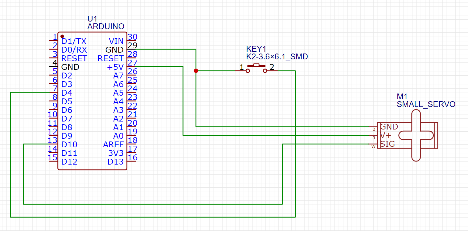
This would be more informative:
The breadboard is missing here, but no one cares.
1 Like
Will keep that in mind. Thank you and sorry for the blurry picture. ![]()
There are valid reasons to use multiple attach and detach statements.
I believe a servo will consume much less power when it is not receiving any pulses. The detach command should put the servo into low power mode (assuming I understand this correctly).
I've personally never used this technique but I think there are valid reasons to use it. I'm not sure but I think the behavior of the servo without pulses may depend on the individual servo. I think there are some digital servos which will actively hold the last position commanded. In this case, there wouldn't be any use to using the multiple attach and detach commands. For the majority of servos, detaching the servo should reduce the power requirements.
Hi,
Valid point, but we don't know if @mruiz02 is using $3 AliExpress or $22 OEM genuine servos.
Also if the arm is under constant load torque and may drift if detached.
@mruiz02 do you still have a problem?
Tom... ![]()
![]()
![]()
![]()
This topic was automatically closed 180 days after the last reply. New replies are no longer allowed.