I’ve spent last 2-months learning from the post on Arduino forum and debugging sketch as much as possible. I’ve already burnt 2 MEGA boards in learning process which brings me to my first post for help. Thank you in advance for your consideration as I’m new to this.
HARDWARE:
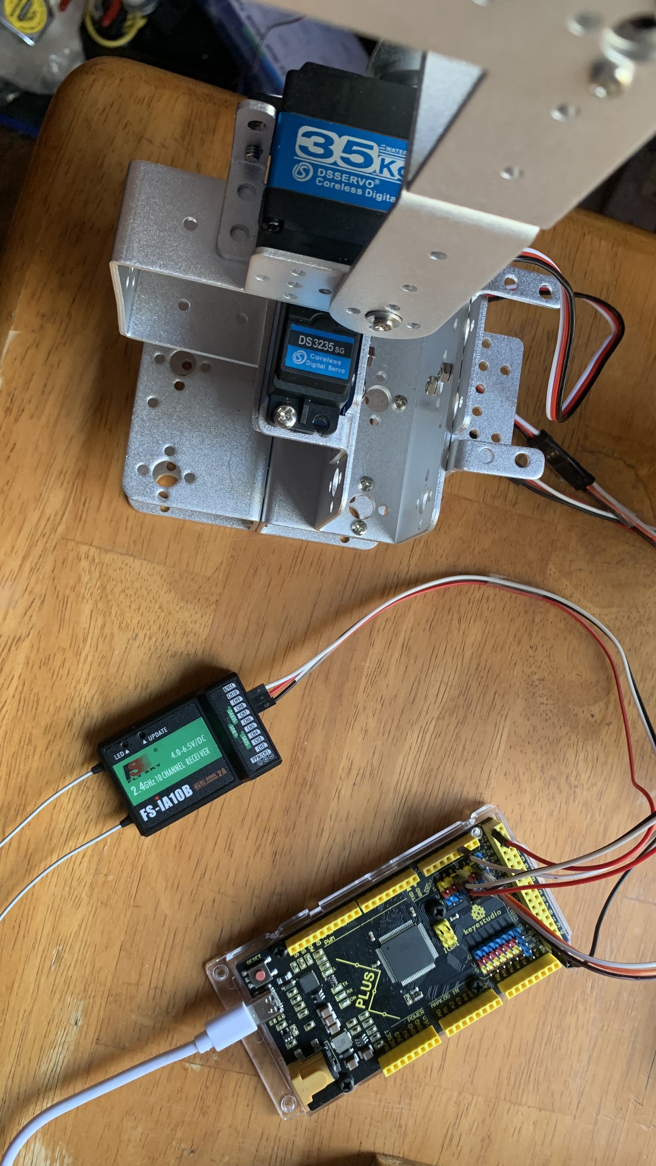
-Arduino MEGA 2560 then switched to Keyestudio PLUS board (servo on pin 2 & pin 5)
-Servos types: 35kg. DSSERVO RDS3235
-FlySky FS-i6x 10ch transmitter / Flysky FS-IA10B 10ch Receiver Support iBUS
-FlySky receiver attached via iBUS to Keyestudio PLUS board (Arduino MEGA).
FYI: Same issues encountered using original Arduino MEGA 2560 board (burning 2 MEGA boards in process), so its not the Chinese board.
SKECTCHES:
WORKING sketches:
Sweep” Arduino example sketch works. So I know nothing wrong with servos.
A sketch prompt for direct angles works, for example:
myServo.write(0); myServo.write(45);myServo.write(90);myServo.write(180);
NOT WORKING sketch:
As soon as said sketch uploaded, servos begin twitching/jittering. Tho I am still able to control servo movement via FlySky transmitter using VRA and VRB knobs the servos move with a twitching/jittering.
POWER:
12V 1amp barrel DC on Arduino MEGA/Keyestudio PLUS board
/*
  Arduino FS-I6X Demo fsi6x-arduino-mega-ibus.ino
  Read iBus output port from FS-IA6B receiver module
  Display values for Channel 5 and Channel 6 (servos attached) on Serial Monitor

  Channel functions by Ricardo Paiva https://gist.github.com/werneckpaiva/

  Additions by DroneBot Workshop 2021 https://dronebotworkshop.com
*/

//Inlcude Libraries

#include <AFMotor.h>
#include <Servo.h>                	// Include Servo Library
#include <IBusBM.h>               // Include iBusBM Library

IBusBM ibus;                      // Create iBus Object
Servo servoVer;                   // Vertical Servo servoVer
Servo servoHor;                   // Horizontal Servo servoHor

int servoVerPin = 5;
int servoHorPin = 2;

int posServoVer = 0;
int posServoHor = 0;

int CH5;
int CH6;

// Read the number of a given channel and convert to the range provided.
// If the channel is off, return the default value

int readChannel(byte channelInput, int minLimit, int maxLimit, int defaultValue) {
    uint16_t ch = ibus.readChannel(channelInput);
    if (ch < 100) return defaultValue;
    return map(ch, 1000, 2000, minLimit, maxLimit);
}

void setup() {

        Serial.begin(115200);
        ibus.begin(Serial1);

        servoVer.attach(servoVerPin);                      // attach servoVer to servorVerPin 5 FlySky channel 6
        servoHor.attach(servoHorPin);                      // attach servoHor to servorHorPin 2 FlySky channel 5

        servoVer.write(posServoVer);                       // start the servo at position 0 middle Vertical
        servoHor.write(posServoHor);                       // start the servo at position 0 middle Horizontal

}

void loop() {

        CH5 = readChannel(4, -100, 100, 0);
        posServoVer = map(CH5, 0, 110, 0, 180);
        servoVer.write(posServoVer);
        delay(100);

        CH6 = readChannel(5, -100, 100, 0);
        posServoHor = map(CH6, 0, 110, 0, 180);
        servoHor.write(posServoHor);
        delay(100);
}