I am trying to implement an algorithm for time synchronization in ESP 32 using LoRawAN.
For that I get correct value of time in microseconds from the LoRa Gateway.
My idea is to start the hardware timer from the time value I get from the gateway.
Is there anyway through which we can start the timer from a known value, and it keeps on automatically increasing as time passes there on, with the resolution of time set in the timer initialized.
I read about using timers with ESP32 in Arduino framework, but could not find any api or implementation, where they initialize a timer with value calculated in the code and then providing it as input to start the timer from there as explained in previous paragraph.
After that I would like to get the timer value to check the synchronization of time with the gateway time. Any ideas in this direction will be also a great help.
Because that time is the time since startup and program code shouldn't be able to modify this.
Just keep the difference between the time you got and the time returned and always add the difference to the value you get by the next call.
BTW, I have doubts that a value in microseconds make sense if transferred by LoRa.
I agree with your logic, but the need for my project is to have a RTC, always in sync with the LoRa Gateway timer counter, thus making synchronization possible. If I wait for the next call to complete and update the value, it will only be in synchronization at that particular instant.
I am calculating the offset between the gateway and lora node timer counter, but the doubt is that, if there is any way i can initialize a timer from there. because then I would be able to drift correction and speed control using the presecaler or frequency divider.
Why do you think you have to wait for the next call? You get a time value from your LoRa gateway and you store the difference you get to the millis() value you get at that moment. Every time you want to get the current time value you use millis() and add the stored difference.
I'm quite sure you wont get a time synchronization by LoRa precise enough to to make a drift correction to the internal timer which is based on crystal. At least not if you get that time synchronization more than once a day.
Unfortunately I misunderstood your suggestions before. You are correct to say that I add the offset in millis() to get synchronization. Rather I amusing micros() for more precision.
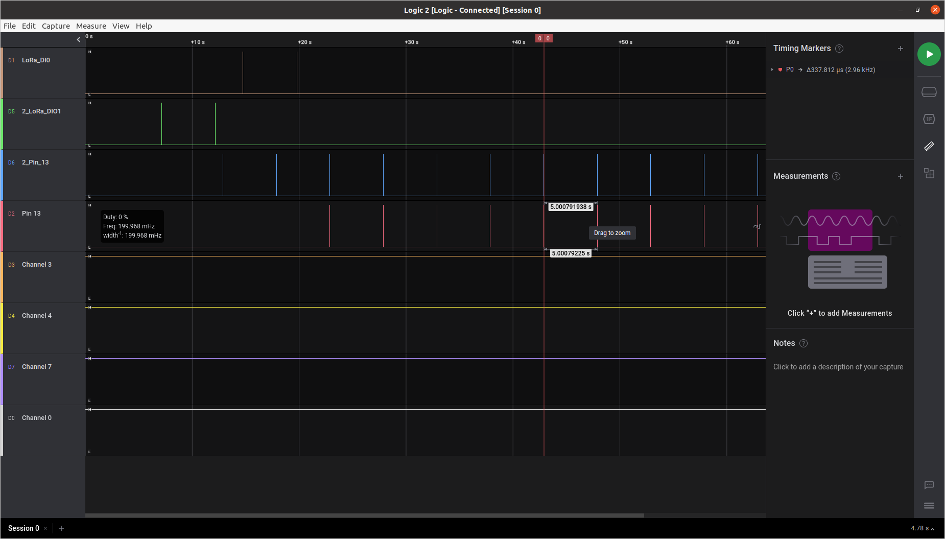
This works when I implement it on one node, but say suppose there are more then one node in the network for time synchronization. To solve and verify this, I produce a pulse every 5 seconds to see if the tick synchronization and verify time sync implementation. I fire an impulse at specific point in time using modulo(%) function, to get the right instant of time to start firing the impulse.
But the implementation is not accurate and reliable. I get variable latencies between tick, from 10ms to 22ms. Which is very high for tick synchronization. Please refer to my below code.
#pragma once

#ifndef PULSE_TRIG_OUT_H
#define PULSE_TRIG_OUT_H

#include <Arduino.h>
#include "lmic.h"
#include "hal/hal.h"
#include "timeControl.h"

/********************************************************************************************************************************************/

// forward declarations
void blink_led();
void pulsePinSetup();

// Decalare variables

const int pulseInterval = 5000000; // interval at which to blink LED (microseconds) 5 seconds
unsigned long previousMicros = 0;  // will store last time LED was updated
bool pulseStart = false;
bool whileStart;
unsigned long synctime;

/********************************************************************************************************************************************/

void pulsePinSetup()
{

  pinMode(13, OUTPUT);

}


// function to get right instant for starting the impulse after synchronisation.
// the time interval between tick is set in pulse interval parameter
void blink_led(signed long sync_time, bool status)
{

  unsigned long currentMicros = micros() + sync_time; // "sync time" is the offset measured between node local clock and LoRa gateway clock


  while ((status && (currentMicros - previousMicros) % pulseInterval <= 1e-1))
  {
    pulseStart = true;
    break;
  }

  if (pulseStart && (currentMicros - previousMicros) >= pulseInterval)
  {
    // Serial.println("LED HIGH");
    digitalWrite(13, HIGH);
    digitalWrite(13, LOW);

    previousMicros = currentMicros;
  }
}

/********************************************************************************************************************************************/

#endif // BLINK_LED_H
Module operation is integer arithmetic and won't be able to produce an output that is smaller than 1 but not equal 0.
Do you think you get the variable latencies there? I'm still convinced that you cannot expect a higher precision from using LoRa, although I'm not an expert in this radio technology.
Lets say there are 2 LoRa ESP32 nodes. They both get time from Gateway to synchronize. After adding the offset in both the nodes, I want to produce impulse from the ESP32 nodes. Such that the impulse (or tick), from both the nodes are synchronized. Meaning the on both the ESP32 nodes, the time when a Digital Pin goes high/down is same. This is one of the application i am trying to develop.
But the problem there will be at what time they should start impulse, so that it they are synchronized. Because it will be good if the synchronization remains independent of the power-on of ESP32 (which is starting point for the micros(), to start counting.)
To solve this lets assume a standard wall clock, where we want to give an output impulse, on 5th min, 10th min, 15 min, 20min........ We can see they are all exactly divisible by 5 (== pulseInterval, in the code). So after adding the offset, the code will check when the the value of time, which leaves 0 remainder or a value close to it. This make the impulses to synchronize at the same time between two ESP32 nodes. (I am hoping to get accuracy below 100 micro seconds)
Maybe the graphical representation, in the current implementation will help to be more clear.
The latencies changes when compared between separate nodes synchronized with the Gateway time. But perhaps this reference could help you to understand more better, for what I am trying to implementLongShoT: long-range synchronization of time
The break statement will end the while loop immediately, which is good because else that would be an endless loop (nothing the condition will change).
Very interesting and amazing what they did to get an extremely precise time distribution. Unfortunately there is no code in the document and no reference to it. Do you have access to that code?
So would you agree that logic with "if" is correct to synchronize the pulses in different nodes independent of their switch on time ? or Are there any other ideas I can try out ?
Unfortunately I don't have access to their code implementation. But If my implementation works, I will surely make it open source
No, as I noted earlier there are other errors in that code part.
The posted code is just an excerpt. If you have just that code it won't do anything.
In the posted code you probably have to inline the currentMicros variable (into the while condition), change from micros() to millis() and change the module calculation to a simple >.
But that's a lot of guessing because I haven't seen the surrounding code.