![]() Hello
Hello ![]()
I'm a newbie to using arduino or any electronics whatsoever...
I am currently trying to test out the ADXL213EB accelerometer I have purchase from Analog Devices.
The code I am using is:
const int xpin = A1;
const int ypin = A0;
void setup()
{
Serial.begin(9600);
}
void loop()
{
Serial.print(analogRead(xpin));
Serial.print("\t");
Serial.print(analogRead(ypin));
Serial.println();
delay(100);
}
Accelerometer spec sheet:
http://www.analog.com/static/imported-files/eval_boards/53621793629198ADXL213EB_0.pdf
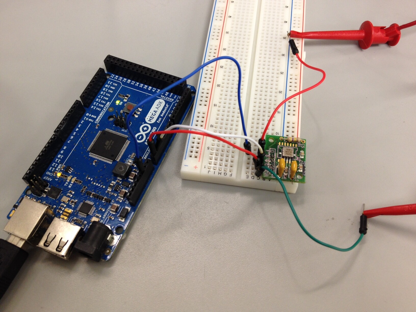
I have attached a photo of the setup that I have right now.
The green wire is connected to the positive probe of a 5 V power supply.
The top red wire is connected to the negative probe of a 5 V power supply.
The blue wire is connected to ground of the arduino and accelerometer evaluation board.
The white wire is for x-axis.
The bottom red wire is for y-axis.
Using this setup with the code above, I am getting a reading but only 2 values (1023 and 0) are showing for both x and y axis.
When this setup is used with a oscilloscope, I get proper duty cycle reading.
What is the problem?
THANKS IN ADVANCE!