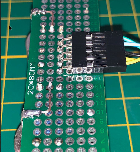
I don't like soldering wires directly into the PCB holes, because the soldering process makes flexible wire more brittle. If you need to handle the assembly during debugging, you're very likely to have wires break right at the PCB surface, which can lead to damage due to unexpected short circuits.
One solution is to add a small clamp made from bare hookup wire. This clamp is insulated from the working wire(s) using a bit of heat-shrink tubing to prevent damage to the insulation, and the clamp itself is soldered to the PCB.
This method provides a very strong and safe mechanical anchoring, even for high-voltage applications.
Here’s the method applied to a MEGA2560:
4 Likes
A second method consists of crimping the wires onto JST terminals, then bending the connector pins before soldering them. This also provides a very strong attachment that resists pulling forces and vibrations.
1 Like
In that case, I usually just encase the solder joints, wire, and wire casing all in one large blob of hot glue. Immobilizes everything.
1 Like
I thread the wires though extra holes I add to the PCB:
(I don't know whether that shows up very well. The wires (insulated part) go down through the right-hand vias, and the bare wire comes up through the left-hand hole, where it is soldered.)
5 Likes


