Short circuit test bench and connectivity tester

Hi all,
I need to prepare connectivity and short circuit tester.
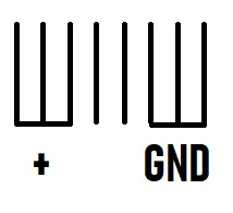
I tried with set port like Output and give HIGH on one of them, then read others to find short circuit, but without success. Can you support me about this. I need to check:

  • first 3 pins are short circuit;
  • last 3 pins are short circuit;
  • 2 middle pins are alone and don't need to short with others;
    If previous conditions are TRUE one led is blink GREEN, else other led Blink RED.
    Do you have any ideas about this. I prepare a lot of actions, but till now without success.

short.jpg

Schematic? Code? Please supply more information as per forum rules.

Hi,
The sample code is below. I think to need to make 8 OUTPUTS and give HIGH level of only one OUTPUT and then check other outputs on Input pins?
Do you think its a good idea?

int groundPin = 0;
int powerPin = 1;
int dataPlus = 2;
int dataMinus = 3;
int redLed = 4;
int greenLed = 5;
//int buttonPin = 13;
//int readGroudPin = 9;
//int readPowerPin = 10;
//int readDataPlus = 11;
//int readDataMinus = 12;
//double analogGroundPin = A0;
//double analogPowerPin = A1;
//double analogDataPlusPin = A2;
//double analogDataMinusPin = A3;
void setup() {
pinMode(groundPin,OUTPUT);
pinMode(powerPin,INPUT);
pinMode(dataPlus,INPUT);
pinMode(dataMinus,INPUT);
pinMode(redLed,OUTPUT);
pinMode(greenLed,OUTPUT);
//pinMode(buttonPin,INPUT);
//pinMode(readingPower,INPUT);
//pinMode(readingGround,INPUT);
//pinMode(readingDataPlus,INPUT);
//pinMode(readingDataMinus,INPUT);
}
void loop()
{
int stateGreenLed = digitalRead(greenLed);
int stateRedLed = digitalRead(redLed);
// int StateGroundPin = digitalWrite(groundPin,HIGH);
if(digitalRead(powerPin) == 0 & digitalRead(dataPlus) == 0 & digitalRead(dataMinus) == 0)
{
digitalWrite(greenLed,HIGH);
}
else
{
digitalWrite(redLed,HIGH);
}
}

You need to explain in detail exactly what it is you are trying to do? Checking short circuits on what? A schematic would really help.

Ron

I attached the schematic in my last posts

neo_nedo:
I attached the schematic in my last posts

Nope, that is a meaningless doodle! You need to give more information about what you are ACTUALLY trying to do, with what and to what. I have read your posts a number of times and it still doesn't help.

I think you are on the right track.
I’d start by moving things off pins 0, 1, keep those clear for serial comm.

Then in loop: (you’ll to fix the autocorrecting going on here, and I’m going to simplify my example as in1, in2, in3, in4, and out1, out2, out3, out4)

Void setup():
//set pinModes for inputs
PinMode(in1, INPUT_PULLUP); // repeat for all 8 cable pins, ensures only 1 active output at a time, no 2 signals competing against each other
PinMode (redLed, OUTPUT);
DigitalWrite (redLed, LOW); // assumes LOW = off
PinMode (greenLed, OUTPUT);
DigitalWrite (redLed, LOW);
}
Void loop():
// test for shorts continuity of a signal, and no shorts to other signals
// 4 output test pins, 4 input test pins
//signal 1
PinMode (out1, OUTPUT);
DigitalWrite (out1,LOW); // drive 1 output low
State1 = digitalReadl (in1); // read all the inputs
State2 = digitalRead (in2);
State3 = digitalRead(in3);
State4 = digitalRead(in4);
If (state1 == LOW & state2 == HIGH & state3 == HIGH & state4 == HIGH){ // is the correct signal low?
DigitalWrite (greenLed, HIGH); // maybe flash one time for signal 1, twice for signal 2, 3 times, 4 times, etc.
}
Else { // nope, got a different signal low, or 2 or more signals low
DigitalWrite (redLed, HIGH);  // same flash idea here.
}
Delay (2000); // allow some time to see the test result
DigitalWrite (greenLed, LOW);  // 
DigitalWrite (redLed, LOW);
PinMode (out1, INPUT_PULLUP); // set back to an input for the next signal

// signal 2
// same as above, but out2 as OUTPUT, test for HIGH -LOW-HIGH-HIGH

//signal 3
// same as above, but out3 as OUTPUT, test for HIGH-HIGH-LOW-HIGH

// signal 4
// same as above, but out4 as OUTPUT, test for HIGH-HIGH-HIGH-LOW
}
I'd start by moving things off pins 0, 1, keep those clear for serial comm.

Agreed. That's Arduino 101.

Also, you need to fill in the blanks of "the board" or at least explain more clearly what you are talking about.
If you mean you want to check board traces then say so.
What the inputs and outputs connected to ?