SHT85 and touch screen

Hello,

I’m somewhat new to the programming and libraries for Arduino Uno.

The setup I have is: Arduino Uno with a Velleman 2.8” touchscreen connected directly to the Arduino.

In addition I have an SHT85 sensor connected through the I2C lines, SCL and SDA because these lines are not used by the touch screen.

I have the sensor working if I read its data through the serial monitor.

I also have the touch screen working with presenting text on it.

Both are running in the same program.

However, if I execute the “sht.Read()” statement, the screen goes blank but I can still read the data from sensor on the serial monitor.

The question I have is, how can I make this work on the touch screen?

The program listing is below.

Thanks for any help,

Ron

#include <Wire.h>

#include "SHT85.h"
#define SHT85_ADDRESS         0x44
uint32_t start;
uint32_t stop;
SHT85 sht(SHT85_ADDRESS);

#include <MCUFRIEND_kbv.h>
MCUFRIEND_kbv tft;       // hard-wired for UNO shields anyway.
#include <TouchScreen.h>
const int XP=8,XM=A2,YP=A3,YM=9; // Touch screen I/O
const int TS_LEFT=918,TS_RT=107,TS_TOP=67,TS_BOT=902;  // For landscape
TouchScreen ts = TouchScreen(XP, YP, XM, YM, 300);
TSPoint tp;
#define MINPRESSURE 150
#define MAXPRESSURE 1000
#define SHT85_ADDRESS         0x44
#define BLACK       0x0000  ///<   0,   0,   0
#define NAVY        0x000F  ///<   0,   0, 123
#define DARKGREEN   0x03E0  ///<   0, 125,   0
#define DARKCYAN    0x03EF  ///<   0, 125, 123
#define MAROON      0x7800  ///< 123,   0,   0
#define PURPLE      0x780F  ///< 123,   0, 123
#define OLIVE       0x7BE0  ///< 123, 125,   0
#define LIGHTGREY   0xC618  ///< 198, 195, 198
#define DARKGREY    0x7BEF  ///< 123, 125, 123
#define BLUE        0x001F  ///<   0,   0, 255
#define GREEN       0x07E0  ///<   0, 255,   0
#define CYAN        0x07FF  ///<   0, 255, 255
#define RED         0xF800  ///< 255,   0,   0
#define MAGENTA     0xF81F  ///< 255,   0, 255
#define YELLOW      0xFFE0  ///< 255, 255,   0
#define WHITE       0xFFFF  ///< 255, 255, 255
#define ORANGE      0xFD20  ///< 255, 165,   0
#define GREENYELLOW 0xAFE5  ///< 173, 255,  41
uint8_t Orientation = 1;    //Landscape
uint16_t ID;
uint8_t Screen = 0;         // Home screen
int Xpos = 0;               //  X position of screen touch
int Ypos = 0;               //  Y position of screen touch
int B1x = 250, B1y = 60, B1w = 60, B1h = 45;  
int B2x = 250, B2y = 135, B2w = 60, B2h = 45;  


void setup()
{
  //  while(!Serial);  //  uncomment if needed
  Serial.begin(9600);
  Serial.println();

  Wire.begin();
  Wire.setClock(100000);
  sht.begin();

  uint16_t stat = sht.readStatus();
  Serial.print(stat, HEX);
  Serial.println();

  uint32_t ser;
  bool b = sht.getSerialNumber(ser, true);
  if (b)
  {
    Serial.print(ser, HEX);
    Serial.println();
  }
  else
  {
    Serial.println("Error: could not get serial number.");
  }
  delay(1000);

  tft.reset();
  ID = tft.readID();
  tft.begin(ID);
  tft.setRotation(Orientation);
  tft.fillScreen(BLACK);
  Screen = 0;
  tft.setCursor(20,75); tft.setTextColor(WHITE, BLACK); tft.setTextSize(2);
  tft.print("TEMPERATURE (C):");
  tft.setCursor(20,150); tft.setTextColor(WHITE, BLACK); tft.setTextSize(2);
  tft.print("REL. HUMIDITY (%):");
  tft.drawRect(B1x, B1y, B1w, B1h, YELLOW);
  tft.drawRect(B2x, B2y, B2w, B2h, YELLOW);

  delay(100);
}  

void loop(){
  sht.read();
  
  tft.setCursor(250,75); tft.setTextColor(WHITE, BLACK); tft.setTextSize(2);
  tft.print(sht.getTemperature(), 1);
  Serial.print("\t");
  Serial.print((stop - start) * 0.001);
  Serial.print("\t");
  Serial.print(sht.getTemperature(), 1);
  Serial.print("\t");
  Serial.println(sht.getHumidity(), 1);
  delay(100);    
}

Does not matter, you can have many I2C devicdes on one bus. There is a limit due to power but expanders solve that.

EDIT, this is wrong.

Have a look at the example code from Rob, the read is followed by more code.

Did you do an I2C scan to vedrify the I2C addresses? Did you test the display c ode with dummy temp and humid values?

Do you have a link to the library you use?

No I have not. Not sure how to do this.

I assumed that if I get data from the sensor and it displays on the serial monitor, the addressing would be okay.

Is that a wrong conclusion?

Rob, I actually used your library, the latest one for the SHT85.

That is a correct assumption, you do not need to verify the i2c address with a scanner program.

Can you show the code you have working with the touch screen.

In your originally posted code, if you increase the delay() in set up to a few seconds, do you see the printed text you want?

Do you need to have
#include "Adafruit_GFX.h"

So first I tried increasing both delay() timers to 5000.

No change.

Then I added #include “Adafruit_GFX.h”

No change.

I can see text until the delay timers expire and then the white screen comes up.

This is when the sht.read() is executed.

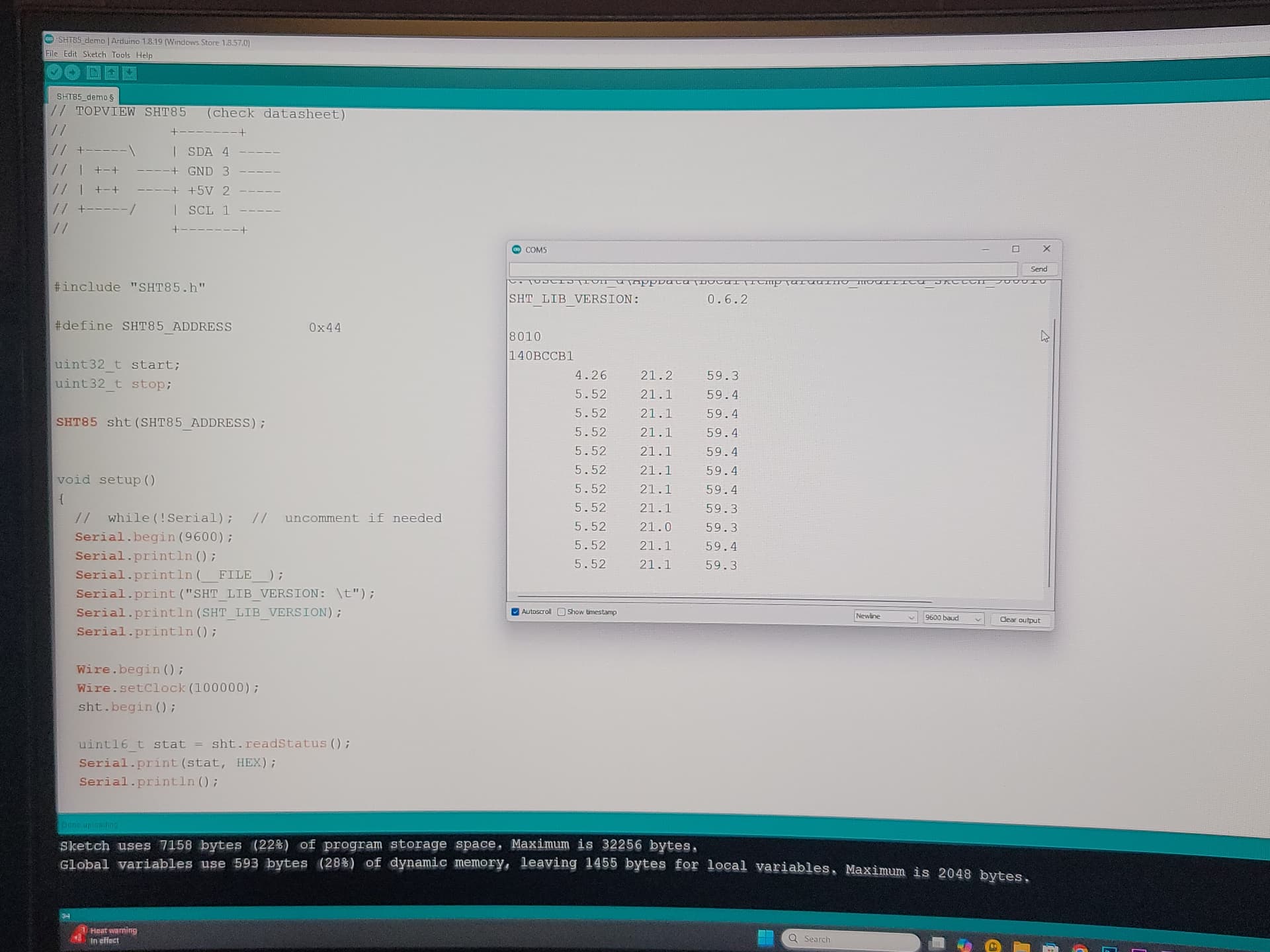
Can you show the output you get when running the sht85/h library demo program.

//
//    FILE: SHT85_demo.ino
//  AUTHOR: Rob Tillaart
// PURPOSE: demo
//     URL: https://github.com/RobTillaart/SHT85
//
// TOPVIEW SHT85  (check datasheet)
//            +-------+
// +-----\    | SDA 4 -----
// | +-+  ----+ GND 3 -----
// | +-+  ----+ +5V 2 -----
// +-----/    | SCL 1 -----
//            +-------+


#include "SHT85.h"

#define SHT85_ADDRESS         0x44

uint32_t start;
uint32_t stop;

SHT85 sht(SHT85_ADDRESS);


void setup()
{
  //  while(!Serial);  //  uncomment if needed
  Serial.begin(115200);
  Serial.println();
  Serial.println(__FILE__);
  Serial.print("SHT_LIB_VERSION: \t");
  Serial.println(SHT_LIB_VERSION);
  Serial.println();

  Wire.begin();
  Wire.setClock(100000);
  sht.begin();

  uint16_t stat = sht.readStatus();
  Serial.print(stat, HEX);
  Serial.println();

  uint32_t ser;
  bool b = sht.getSerialNumber(ser, true);
  if (b)
  {
    Serial.print(ser, HEX);
    Serial.println();
  }
  else
  {
    Serial.println("Error: could not get serial number.");
  }
  delay(1000);
}


void loop()
{
  start = micros();
  sht.read();         //  default = true/fast       slow = false
  stop = micros();

  Serial.print("\t");
  Serial.print((stop - start) * 0.001);
  Serial.print("\t");
  Serial.print(sht.getTemperature(), 1);
  Serial.print("\t");
  Serial.println(sht.getHumidity(), 1);
  delay(100);
}

//  -- END OF FILE --

This example is actually what I used to create my own file.

Was the tft screen on the uno when you ran the successful example?

I noticed, I do not recall any related issues mentioned on GitHub (including related SHTxx libs).
From your post I understand that the SHT85 just keeps working.

Could it be a power problem? How do you power the display?

Hi Rob,

The whole thing is powered through the usb cable from the computer.

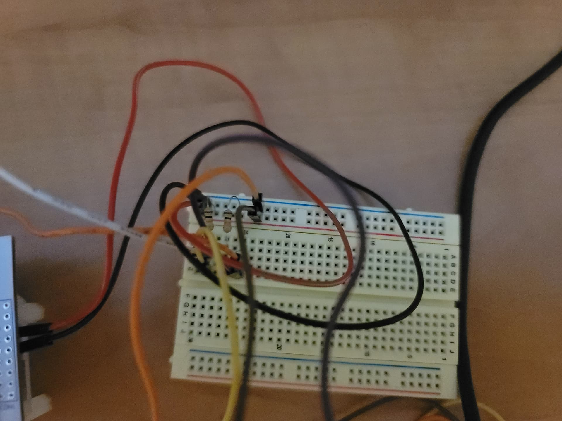
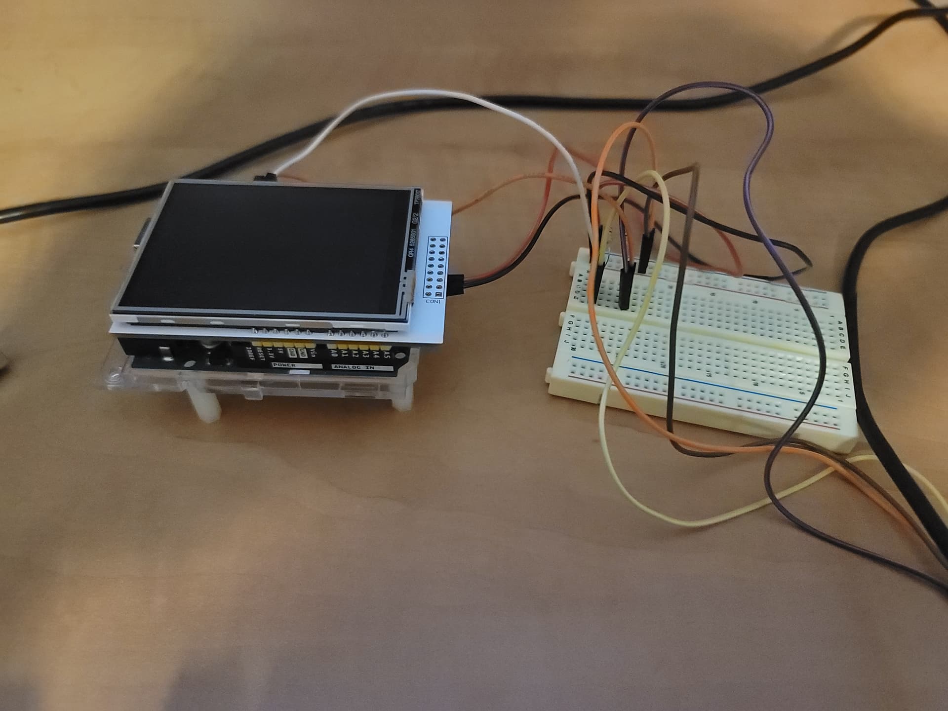
Please see pictures below about the setup.

The whole idea behind this project is to have a little standalone device that you can use anywhere to quickly check temperature and humidity. Especially because the display is stacked on top of the Arduino and the sht85 using the clock and data lines, I thought these would not interfere.

Yes.

The screen works when the “sht.read()” is bypassed.

When it is activated, the data can be viewed on the serial monitor but the screen is blank white.

Investigated some time to find a possible library link, found a possible candidate and had a look at the .h file

There is a possible constructor with default pins.

MCUFRIEND_kbv(int CS=A3, int RS=A2, int WR=A1, int RD=A0, int RST=A4); //shield wiring

As you use default pins in the code you posted, this could explain the problem as the default I2C on an UNO are pins A4 (SDA) and A5 (SCL). So the A4 pin could be the culprit.

Scenario

When the SHT85 library starts to read the device, there will be pulses on the SDA = A4 pin which will trigger the RST (== reset?) pin of the display.

Question

What are the default pins in you MCUFRIEND library?

Hi Rob, thanks a lot for this feedback. This would make sense. I'm at work right now and will take a look at this when I get home.

I'll keep you posted!!

Ron

Yes, conflict with the reset pin on A4 is indeed the issue. The library was designed around using SPI shields and is in conflict with additional use of the i2c bus.

It has been discussed many times on the forum. Many of the solutions involve snipping the reset pin on the shield and tying it high.

Good forum search terms are "MCUFRIEND_kbv I2C" and "mcufriend snip A4".

It's not clear to me if the library can be modified without any pin snipping.
There is the default constructor in MCUFRIEND_kbv.h

public:
//	MCUFRIEND_kbv(int CS=A3, int RS=A2, int WR=A1, int RD=A0, int RST=A4); //shield wiring
	MCUFRIEND_kbv(int CS=0, int RS=0, int WR=0, int RD=0, int _RST=0);  //dummy arguments

And then there is a constructor in mcufriend_shield.h which is indeed included in the .cpp file.

#elif defined(__AVR_ATmega328P__) || defined(__AVR_ATmega328PB__)       //regular UNO shield on UNO
//LCD pins  |D7 |D6 |D5 |D4 |D3 |D2 |D1 |D0 | |RD |WR |RS |CS |RST|
//AVR   pin |PD7|PD6|PD5|PD4|PD3|PD2|PB1|PB0| |PC0|PC1|PC2|PC3|PC4|
//UNO pins  |7  |6  |5  |4  |3  |2  |9  |8  | |A0 |A1 |A2 |A3 |A4 |
#define RD_PORT PORTC
#define RD_PIN  0
#define WR_PORT PORTC
#define WR_PIN  1
#define CD_PORT PORTC
#define CD_PIN  2
#define CS_PORT PORTC
#define CS_PIN  3
#define RESET_PORT PORTC
#define RESET_PIN  4

I think you can leave the dummy constructor alone, and modify the shield constructor.

Thank you very much all for the very valuable feedback.

It works. I disconnected a4 from the connector and connected it to vcc.

Just a quick question though, if the scl and sda are physically connected to a3 and a4, why would the scl and sda be there in addition to a3 and a4?

Again thanks for the support