FT810 with Uno R4 Minima - doesn't work

Good day all,

I am new on that forum. I am writing to You as I need a help. I am trying to make some hobby project. The part of the project is touch screen made by HAOYU-Electronics FT810CB-HY50HD-IPS with the FT810 controller.

Unluckily when I was preparing for that project and when I found this screen I did not figure out that it is quite old one.

Basically I have Arduino Uno R4 Minima and I am trying to make it work with my FT810 screen.
I went through a lot of pages and this forum. I think I have tried all libraries. Starting from FT81x Arduino Library available in the Arduino IDE, GD2, GD3 and finally GD23Z.

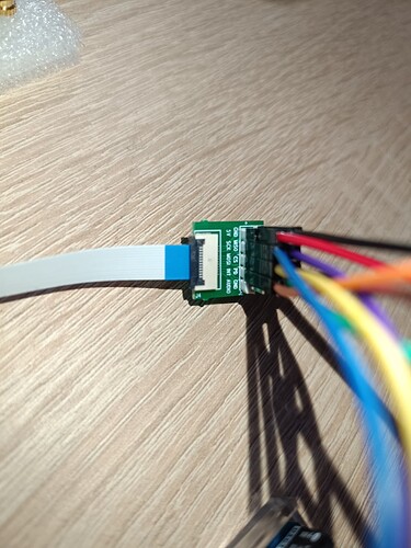
I have connected screen via small removable mini-board card included to the screen and flat cable. As shown below (a keep the cables short as possible).

Current setup of the pins:

FT810 (HotMCU)      Arduino UNO R4 Minima 

MOSI                  pin 11
MISO                  pin 12
SCK                   pin 13
GND                   GND
VCC                   5.0V
CS                    pin 9
PD                    pin 8
INT                   pin 10

When I tried to use FT81x library and its examples. The screen is dead. nothing happens. However as I see (I think) this library is for screen with additional card like below, which I do not have in my version of the screen.

So I followed this thread from the forum Library for LCD - SPI, FT810 ??? - #4 by TFTLCDCyg

It was suggested to use GD2/GD3 library with my screen. So I tried. Unfortunately what I suspect the library is 7 years old and my Uno R4 is too new. I have tried also GD23Z which was slightly never version of the library. But with no luck. I am getting compile errors.

First of all sorry for long description but I wanted to give You as much information about behind problem story.

Summing this up. Like I mentioned above I am getting compile errors like this.

In file included from Documents\Arduino\libraries\GD23Z-master\examples\all_boards\helloworld\helloworld.ino:2:0:
GD23Z-master/GD23Z.h: In member function 'void sdcard::begin(byte)':
GD23Z-master/GD23Z.h:311:9: error: 'class arduino::ArduinoSPI' has no member named 'setClockDivider'
     SPI.setClockDivider(SPI_CLOCK_DIV64);
         ^~~~~~~~~~~~~~~
GD23Z-master/GD23Z.h:311:25: error: 'SPI_CLOCK_DIV64' was not declared in this scope
     SPI.setClockDivider(SPI_CLOCK_DIV64);
                         ^~~~~~~~~~~~~~~
GD23Z-master/GD23Z.h:311:25: note: suggested alternative: 'CGC_SYS_CLOCK_DIV_64'
     SPI.setClockDivider(SPI_CLOCK_DIV64);
                         ^~~~~~~~~~~~~~~
                         CGC_SYS_CLOCK_DIV_64
GD23Z-master/GD23Z.h:387:9: error: 'class arduino::ArduinoSPI' has no member named 'setClockDivider'
     SPI.setClockDivider(SPI_CLOCK_DIV2);
         ^~~~~~~~~~~~~~~
GD23Z-master/GD23Z.h:387:25: error: 'SPI_CLOCK_DIV2' was not declared in this scope
     SPI.setClockDivider(SPI_CLOCK_DIV2);
                         ^~~~~~~~~~~~~~
GD23Z-master/GD23Z.h:387:25: note: suggested alternative: 'AGT_CLOCK_P402'
     SPI.setClockDivider(SPI_CLOCK_DIV2);
                         ^~~~~~~~~~~~~~
                         AGT_CLOCK_P402
GD23Z-master/GD23Z.h:388:5: error: 'SPSR' was not declared in this scope
     SPSR = (1 << SPI2X);
     ^~~~
GD23Z-master/GD23Z.h:388:5: note: suggested alternative: 'SPI'
     SPSR = (1 << SPI2X);
     ^~~~
     SPI
GD23Z-master/GD23Z.h:388:18: error: 'SPI2X' was not declared in this scope
     SPSR = (1 << SPI2X);
                  ^~~~~
GD23Z-master/GD23Z.h:388:18: note: suggested alternative: 'SPI'
     SPSR = (1 << SPI2X);
                  ^~~~~
                  SPI

exit status 1

Compilation error: exit status 1

As far as I understood, missing declarations and members were in older version of SPI of UNO R3. Am I right? Same is on all GD libraries versions.

Anyway is there any chance to run FT810 screen on Uno R4? Maybe someone has some working library or can suggest something. What is strange for me GD library is seeking for sdcard function where my screen has no SD card reader. Hopefully i did not spent money for nothing.

BTW. If You could suggest some similar TFT touch screen 5-7 inch which will not make so many troubles and will not cost fortune. What if could be?

I hope I did not mess up to much this thread. Thank You in advance for any advice or help.

Best regards!

I have never tried any touch screen with arduino but if I had to, I would probably pick something like this with Esp32 on board.

Let's get some information.
The board you have is an Arduino UNO R4 Minima. Show me with a screen grab that board selected in the Drop Down or the Tools menu.
Take a close up photo of the tiny board, both sides and post, also take photos of the front and back of the display board and post. Once we have some basic hardware info we can see if a library exists. I just did a quick Library lookup and got one library. I tried the 'Hello World' sample and other than some insignificant warnings it compiles fine. This is one of many SPI screens so should work but if you are missing the controller card then it is a boat anchor. Until we can see the small card to determine if it is a controller or not my fear is this is a dead duck.

The gameduino library was designed for AVR microcontrollers working with the SD library. In all this time, my friends and I have tried to migrate it so that it is functional on ARM microcontrollers such as STM32 and teensy 4.1/4/3.6 but working with the SdFat V2 library.

The latest version is GDSTx and 100% functional with teensy 4.1, teensy 4, teensy 3.6, STM32 F1/F4/F7 and partially with STM32 H7. In the last two months I was able to get it working on the RPi Pico. All these boards work with the SdFat library for multimedia management.

The UNO R4 Minima has an ARM cortex M4 microcontroller, in theory it could work, I have compiled the Helloworld_border example in the IDE 1.8.19 and the errors that the compiler throws have to do with the definition of the R4 Minima that the Arduino IDE uses and with the screen size. Perhaps later the errors derive from the definition of SPI pins for the screen and the external microSD reader.

Can you tell me how the Arduino UNO R4 Minima board is defined in the Arduino IDE?

Hello again,

first of all thank You @sonofcy & @TFTLCDCyg for your inputs to this topic.

In the Arduino IDE i am choosing bellow board.

I have tried to compile the same code choosing Arduino Uno (old version) and it is compiling without any problem.

I did the pictures which asked @sonofcy see bellow. Honestly I do not know why i did not see this before but on my screen it is written FT800CB and I was buying FT810 version, but this is other story, anyway the code is not compiling.

I am using the newest version of IDE 2.3.4 i hope this is not an issue.

Thank You for any further assistance.

Hi,

I have some update to above.

I have contacted the supplier of the screen and he confirmed that neverthless the information on the board that it is FT800CB this is FT810CB version.

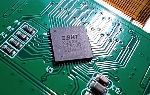
I have checked the chip on the board and that's true (FT810Q by Bridgeteck).

From your experience and the feedback from the supplier I don't expect it to work. Why not just get something more modern? In any case I can't be of any more help so goodbye.

Thank You, I have bought Arduino Uno (older version) and we will see, tomorrow I should get it, then I will make some tests. I know that I should go with more modern screen. My bad, I did not looked on the release date and forum, tutorials create time. I realize that after I bought the TFT screen. So now I am trying to run it somehow. Maybe going back with the Arduino version will be some solution.

In version 2.0 of my project I will think about more modern stuff :slight_smile:

That screen could theoretically work well with the R4 Minima, since it has 5V control logic. The PCB says FT800CB because it is compatible with FT810CB.

Now, you have in your hands a screen that far surpasses the typical modern TFT that everyone recommends for their Arduino projects: ILI9341, ILI9488, etc. Of course, there are very polished libraries that can make good use of them, but they are not for everyone, the level of programming required to customize the examples is very high.

The display manufacturer made that series of TFTs following the FTDI chip standard. In early designs, AVR arduinos were thought of, not ARM arduinos. The errors you point out have more to do with the absence of the specific definition of the plate you want to use.

The GD23Z library has the bases for ARM boards, but the instructions for AVR also remain in it. Since the R4 Minima is not defined within the library, it is assumed that it is an AVR arduino, not an ARM arduino. Upload to the post, the GD23Z library compressed in zip, just as you want to use it.

This is a 3.5" FT813 display connected to a Teensy 4.1 board using the latest GDSTx version. FT813 is the capacitive touch panel version and FT810 is the resistive touch panel version. So far I have not seen a typical screen for arduino do something even similar

So if I understood You right, library is not recognizing my Arduino UNO R4 and due to that it treating it like some AVR Arduino. So following that if I will adjust library to recognize correctly the board it should work, am I right?

I was looking into the code, but I think this can be slightly above my knowledge and skills.

The wiring

FT810 (HotMCU)      Arduino UNO R4 Minima 

MOSI                  pin 11
MISO                  pin 12
SCK                   pin 13
GND                   GND
VCC                   5.0V
CS                    pin 10
PD                    pin 9

Try with the GDSTx library updated
Use the example: 1.Basic/Helloworld_border

IDE Arduino: 1.8.19
Board name: ARDUINO_UNOR4_MINIMA
TFT id (SizeEVE=510): 5" HotMCU FT810CB-HY50HD-IPS

Connect your FT810 to UNO-Minima, upload the sketch, and see what results you get. I do not have the screen or the motherboard to test, so you will do me a great favor by allowing me to check the settings from a distance. Upload a photo with the result, fingers crossed it works

1 Like

Hello @TFTLCDCyg I do not know what to say. Your the best.

I have connected the screen as You said, compile the sketch without any errors and the screen alive.

I do not know how to thank You for such a quick solving of the problem.
I own You some beer :beers:

BTW. When I was reading other topics I had a feeling the you can be the right person.

I compile it on IDE 2.3.4
for Arduino UNO R4 Minima
with TFT FT810CB-HY50HD-IPS

One more question if I can. I know it is slightly of topic but I hope I will not brake some rules if I will use this topic for below question.

Further I would like to connect the SD Card Reader Module, as I understood I can use the same MISO, MOSI and SCK pins just CS must different for selecting the communication.
I read about sensitivity of those screens for length of the cables so can additional module on that lines interrupt the screen functioning?

Thank you in advance.

Wow, now I see in full color what I imagined when making the adjustments in the library. Excellent.

We can continue in this thread, since it is part of your project.

It seems to me that the most recent SdFat library compiles without errors with the SdInfo example. Connect a 5V microSD reader, use pin 7 for CS-SD. Since the UNO-Minima only has one SPI bus, like the arduino UNO, I don't see any problems with the SPI bus being shared between the FT810 and the microSD reader.

Try to get the microSD reader to work without connecting the screen. You can use a 64 Gb microSD memory with exFat format. Along with the GDSTx library there is a folder with image files that you can save to the microSD memory for testing.

PD: The touch panel can be calibrated, I just need to know which screen is displayed when loading the following sketch:

#include <GDSTx.h>

void setup() 
{
 GD.begin();
 GD.self_calibrate();
}

void loop() {
  GD.ClearColorRGB(0x00aa00); 
  GD.Clear();
  GD.get_inputs(); 
    GD.cmd_text(GD.w / 2, GD.h / 2, 31, OPT_CENTER, "Hello world");
  GD.swap();
}

Take a photo of the first image generated by the TFT.

Then proceed with the calibration instructions, there are only three points. Please clarify something for me, does the R4 Minima have EEPROM?

1 Like

Hi all. It seems that my joy was too optimistic and too quick. Today during some playing when I wanted to reconnect the TFT screen probably I did some mistake, I not sure exactly as I thought that I have put all cables correctly. Anyway unfortunately the screen is dead now :frowning: I was thinking that maybe some bad connection but i have checked several times and also I measured that the connections are passing from board to TFT, voltage is 4.8V so I think right. Before was working like that.

Is it possible that if I mixed some signal cables that I have burned something in the TFT screen?

I am still trying but doesn't look promising

As I see according to documentation R4 has 8 kB of EEPROM.

Update of the situation:

Good news is that the arduino UNO R4 board working normally. I managed to connect SDCard reader and using SdFat library run it. I save some test file and read it.

What I have found is that when I have connected it together with TFT screen, something is blocking. Each other. It seems that SDCard reader is trying to connect to TFT screen. I have the CS pin separate for each device. TFT as previously on Pin 9 and SD card on Pin 7. When I disconnect the TFT screen SD card is working fine. Any clues?

Going back the screen, I think I need the new one. I have changed all cables, I connect only TFT screen and try Hello world sketch. I measured the power. I think I did all what i could. Beside direct connection to the TFT board. But if all checked pins signals are passing I doubt this in an issue.

Probably I did something wrong when I used today morning the extension for Arduino ( Gravity - Screw Shield V2)


BTW. Its really helpful thing. I can recommend.

Anyway I assume that during reconnecting of the cables I mixed up something, unfortunately when it was not working I have removed all connections and reconnect again. So I do not know what i did wrong :frowning:

Unfortunately I am not enough skilled to perform deep investigation in the TFT PCB and modules to find an issue, so like I said at the beginning most probably I will need another TFT screen. Hobby cost :slight_smile:

You have to be very careful that the wiring is as short as possible between the screen and the SPI bus. I recommend removing all the wiring.

Thinking that there was no serious failure when you reconnected your TFT yesterday, and that it is something software, not hardware. I think we can explore that possibility.

Load a sketch so you can see that your R4Minima is working well, the quickest thing is an LED blinking test.

Reconnect the TFT as the first time.

Load the example of checking the touch panel that I uploaded in the previous post. With this example we can verify that the TFT and its touch panel respond.

Possibly there is some detail with the touch screen. I am going to review some adjustments in the calibration routine, I will add the necessary support so that the panel calibration vector is stored in the EEPROM of the R4Minima.

If the TFT still does not respond, we can still check if it is working correctly. The touch vector is a series of 25 numbers that can be stored in the eeprom. Please upload the example of eeprom_read from the EEPROM library and share the screenshot of the serial monitor, the first 25 records are of interest.

If the first register is 0, the library will try to load the calibration routine, but this point has not been corrected so that it responds to the FT810 TFT

We can interrupt the calibration routine, saving in register 0 of the eeprom a value other than zero and less than 255.

Then reload the sketch with which the TFT worked the first time

Thank @TFTLCDCyg for above.

I have short cables as You can see on the picture:


I did not connect anything to the arduino board beside the screen.

Regarding the blinking Led (do You mean on Arduino board?). If yes, than it is still light, but not as bright as during upload.

I have tried first example, and the second which was with calibration and I have found that the program is starting and when it is reaching GD.Begin() it is freezing.

My code:

#include <GDSTx.h>

void setup() 
{
  // Activating debugging
  Serial.begin(9600);
  while (!Serial) {
    ;  
  }

  Serial.println("Serial initiated");
  Serial.println("Initiating GD.begin()");
  GD.begin();
  Serial.println("Initiating GD.self_calibrate()");
  GD.self_calibrate();
}

void loop() {
  GD.ClearColorRGB(0x00aa00); 
  GD.Clear();
  GD.get_inputs(); 
    GD.cmd_text(GD.w / 2, GD.h / 2, 31, OPT_CENTER, "Hello world");
  GD.swap();

}

Outcome in the serial monitor

and nothing else, so it is not reaching the calibration even.

Yesterday I was playing with the screen for some time, different codes and was ok. Calibration was working fine, I was reading the inputs x and y to Serial with no problem.

Today screen is just black.

Regarding this reading of the EEPROM i execute that sketch but I am not sure if I did it right.
All register are 255.

So if I am right the screen is not responding.

Like I mentioned before, I will say the Arduino board is fine and all MOSI, MISO, SCK lines. As SDCard Reader on those ones working fine.

I have been in that same place where you are, due to an error connecting a thread where it should not go and the screen not responding. It has happened to me several times.

You should also be very careful with static electricity, try to have an antistatic bracelet on hand before handling the components.

I updated the GDSTx library to add the touch panel calibration routine, try again to see if there is an answer.

Yes it is. All connections as previously given by you.

FT810 (HotMCU)      Arduino UNO R4 Minima 

MOSI                  pin 11
MISO                  pin 12
SCK                   pin 13
GND                   GND
VCC                   5.0V
CS                    pin 10
PD                    pin 9