I had recently taken up a project and was wondering if I could get some help to program part of it, as I have experience in programming, but not with arduino. The idea is to make a safety lock for machine shop tools.
For this project I'm going to use a drill press, so here's the hardware setup:
-Arduino UNO board, color sensor, and button will all be connected and placed on the drill press (these will most likely be all put into a box to conceal it all)
-A 5v wire will be connected from the arduino (I think) to the relay
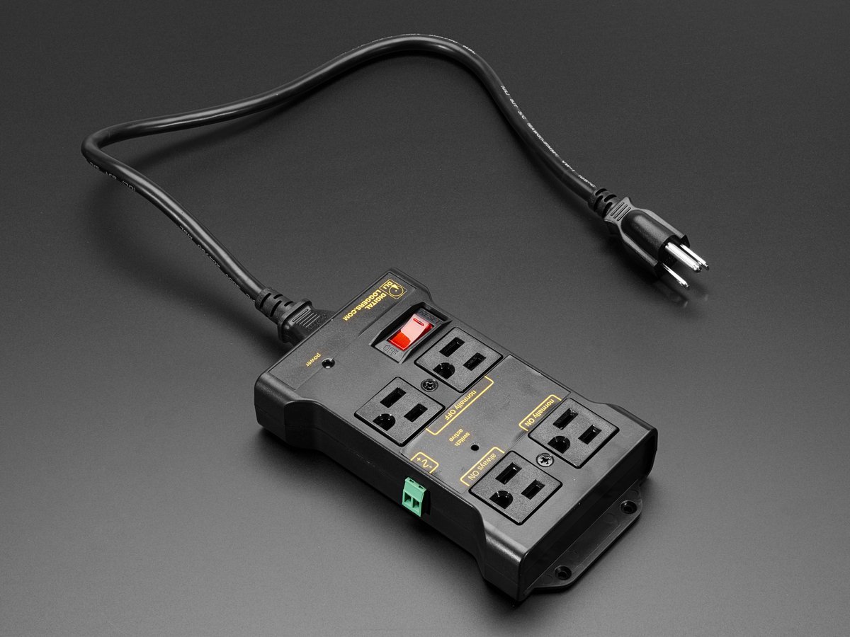
-The 120v wire stemming from the drill press will have the AC Plug cut off, and the severed end will be connected to the relay
-Another 120v will be plugged into the wall and the other end is connected to the relay.
(Essentially the relay will be in between the two 120v wires to power the machine tool, and the 5v from the arduino will be what turns the relay on and off, therefore it being powered controls whether or not the 120v will get power between the outlet and drill press)
vvvvv Here's the pseudocode vvvvv
-Waits until a button is pressed
-Color sensor scans for the retro reflective tape on safety glasses)
-If it detects the tape, begin a 5 minute timer (other functions need to be able to run- while this timer is active)
-Sends power to a 5v wire, to make the relay close the circuit, so power will flow from the 120v wire (from the machine) to the 120v wire plugged into the wall.
-After the 5 minutes is over, the relay needs to open, so the device can't be powered again until the button is pressed again and the the sensor scans again.
Currently, we have the color sensor, arduino UNO board, retroreflective tape, safety glasses, machine tool to test with, and the necessary power cords.
I'd appreciate any help for how to write the code, as well as any advice for how to improve the hardware setup. I have looked at many tutorials, but none of them have seemed to help to the extent that I need.