Hello everyone,
I'm currently testing the SIM800L module with my Arduino UNO, but I'm having a problem: the module's LED flashes every second, which means that it's powered but can't connect to a network. What bothers me is that no data or response appears in the serial monitor.
Checks performed:
- The SIM card is inserted in the correct orientation.
- I used an adapter for the SIM card because it was too small.
- I disabled the SIM card's PIN code using my phone.
- The Arduino can send data to the serial monitor (tested separately with
Serial.println("Hello, World!")).
Power supply for the SIM800L:
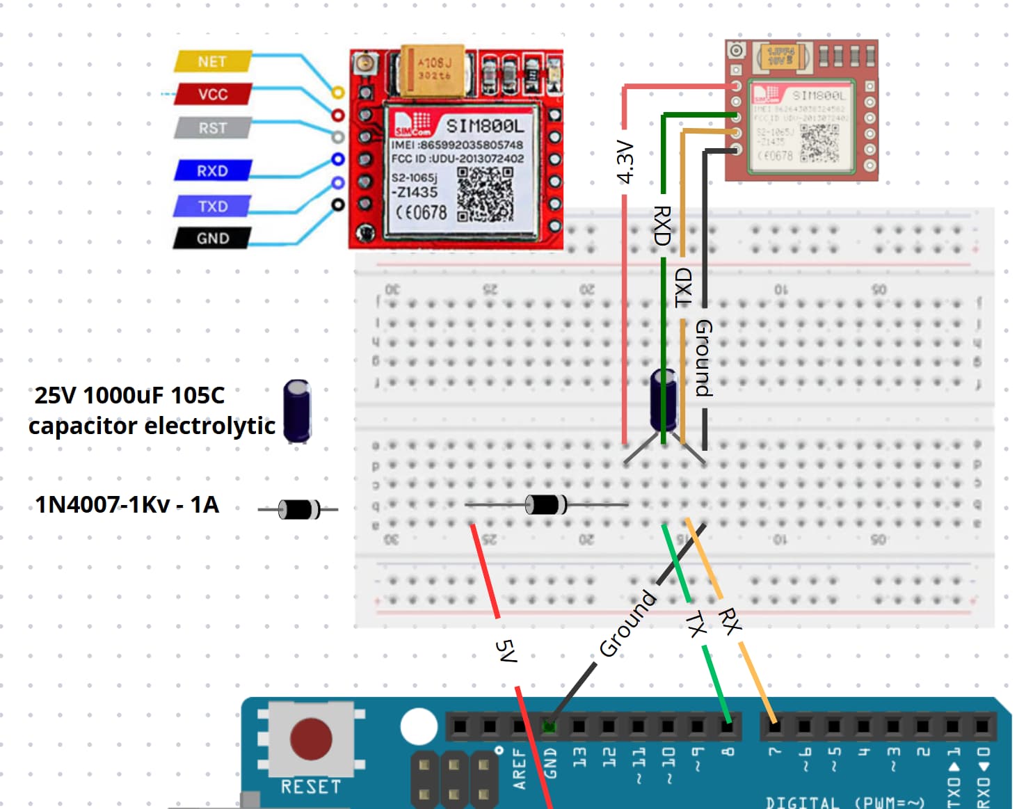
I know the SIM800L is very sensitive to power and requires a voltage between 3.7V and 4.4V.
- I used a diode to lower the voltage to 4.3V.
- I added a capacitor to handle current peaks.
Wiring:
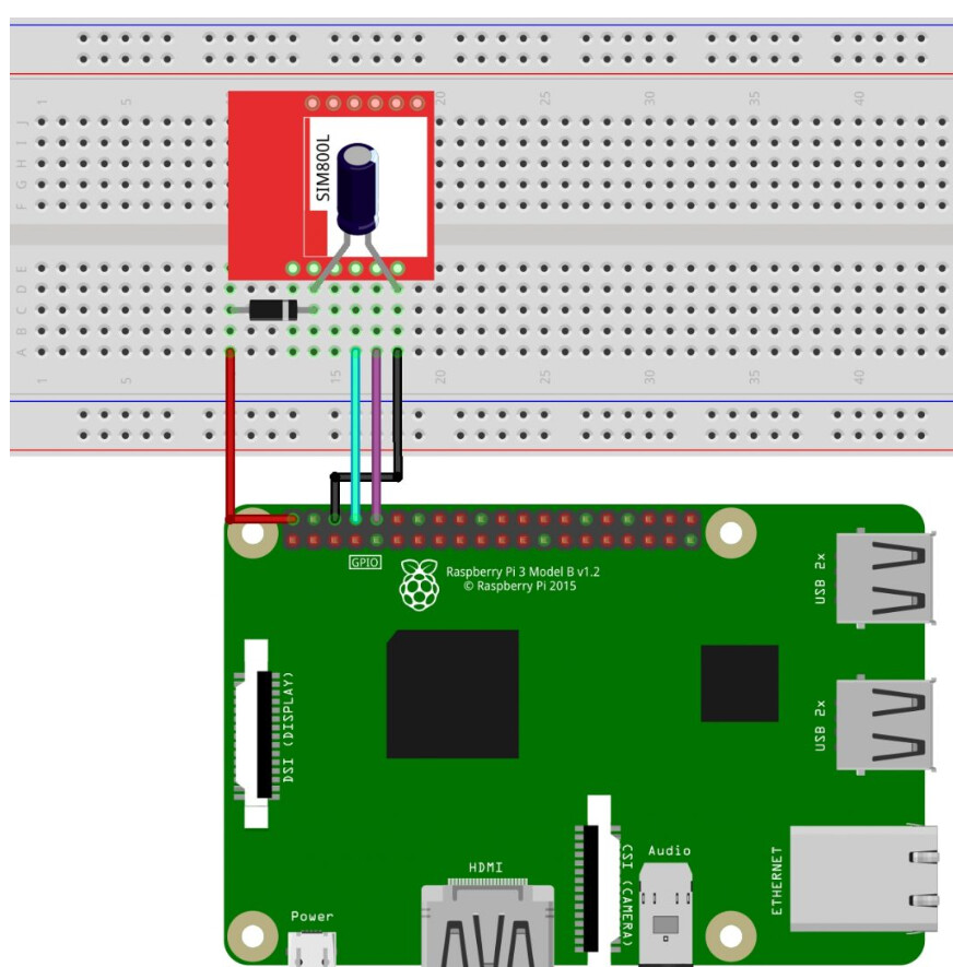
I followed the schematic from this tutorial. In the article, the author uses a Raspberry Pi, but the principle should theoretically be the same—we just need a voltage between 3.7V and 4.4V.
![]() Comment brancher et utiliser un module GSM SIM800L avec le Raspberry Pi (sans batterie).
Comment brancher et utiliser un module GSM SIM800L avec le Raspberry Pi (sans batterie).
Here is the schematic from the tutorial that I used as a reference:
And here is my own wiring diagram:
#include <SoftwareSerial.h>
SoftwareSerial sim800l(7, 8); // RX, TX

void setup() {
  Serial.begin(9600);
  sim800l.begin(9600);
  delay(1000);

  sim800l.println("AT"); // Communication test
  while(sim800l.available()) {
    Serial.write(sim800l.read());
  }
}

void loop() {
  // Handle AT commands here
}
Questions:
- Why is the serial monitor not receiving any response from the SIM800L? If I can get error messages, I'll have made progress and it'll be easier to debug.
- Is my power supply setup correct, or should I try a different solution?
- Are there any other points I might have overlooked?
Thanks in advance for your help! ![]()