@xfpd Hi xfpd,
I´ve tried it with an ESP32 and the gsm shield seems to work normal. The netlight blinks every 3 seconds but I don´t recieve anything. Not even OK.
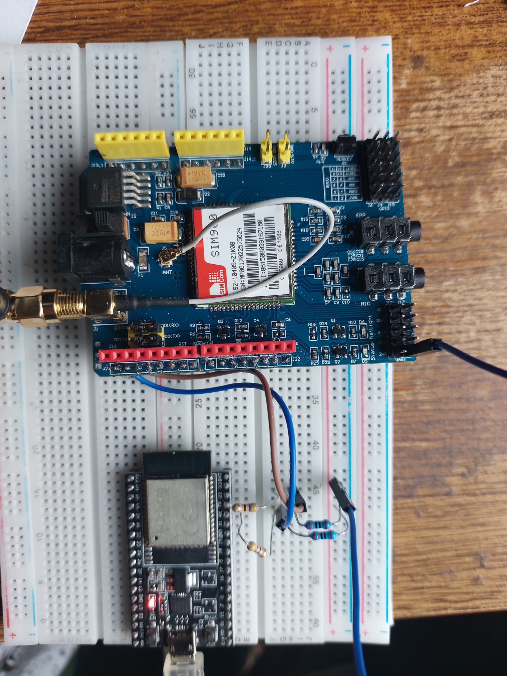
This is an image of the esp32 connection to reduce the voltage the gnd is connected with a 270 Ohms resistor and the tx/rx with a 470 Ohms connected to the pin. So I´ll get 5Vx470/(470+220) = +- 3.17V.
@xfpd Hi xfpd, he´s working now. I used other Gpio´s and another sketch. I´ll put it later here with the wiring. I´m going to use it as an alarm which sends an sms when the power falls out.
Thank you for the interest and your time.
Greetings Rudy.
@xfpd Like I said this is the sketch that's working for me.
#include <SoftwareSerial.h>
// Wiring
/*
* GSM shield            Arduino            RY1:5V             RY2             T1:NPN
*    5V                  VINN              5V                 COM
*    GND                 GND               T1:E               GND            B
*    12V                                                      12V
*    J1                   7
*    J2                   8
*    11                   11                                  NC
*                         13                                                 C
*    PWRKey                                COM
*    PWRKey                                NO
*    2V8                  A5
*    11                   A3
*
*/
//Create software serial object to communicate with SIM900
SoftwareSerial GSM900(7, 8);  //SIM900 Tx & Rx is connected to Arduino #7 & #8
char incoming_char = 0;
int pinStartUp = 13;  // Used to start up the GSM shield
int pinIn = 11;       // controlates if there's still power on the relay
int analogPin = A3;   // from RY2 NO
int valA = 0;         // variables to store the readed value
int valB = 0;
int val = 0;        // integer to read digital value, comes from relay NC
int powerPin = A5;  // analog pin5 used to measure if the module is powered and needs a restart from 2V8 gsm-shield
int smsVal = 0;
int counter = 0;
int count = 0;

void setup() {
  pinMode(pinIn, INPUT);
  pinMode(pinStartUp, OUTPUT);
  //Begin serial communication with Arduino and Arduino IDE (Serial Monitor)
  Serial.begin(19200);
  Serial.println("Initializing...");
  //Begin serial communication with Arduino and SIM900
  GSM900.begin(19200);
}

void loop() {
  val = digitalRead(pinIn);
  valA = analogRead(analogPin);  // read the input pin
  valB = analogRead(powerPin);
  if (val == 1 ) {
    resetCounter();
  } else if (val != 1 && counter >= 49 && smsVal < 2 && valA < 1000) {
    if (smsVal < 1) {
      // An error occured, send sms
      sendSms();
      delay(1000);
      Serial.println("Sending sms....");
    }
  } else {
  }
  if (valB < 100) {
    count++;
    if (count >= 15) {
      /*Serial.print("Count = ");
      Serial.println(count);
      Serial.println(valB);*/
      startUp();
    }
  }
  updateSerial();
  if (valA == 0 && counter < 50) {
    counter += 1;
  }
  delay(1000);
  if (counter != 0) {
    Serial.print("Counter = ");
    Serial.println(counter);
  }
}

void updateSerial() {
  delay(500);
  while (Serial.available()) {
    GSM900.write(Serial.read());  //Forward what Serial received to Software Serial Port
  }
}

void sendSms() {
  smsVal++;
  delay(100);
  GSM900.println("AT");  //Once the handshake test is successful, it will back to OK
  updateSerial();
  GSM900.println("AT+CMGF=1");  // Configuring TEXT mode
  updateSerial();
  GSM900.println("AT+CMGS=\"+ZZxxxxxxxxx\"");  //change ZZ with country code and xxxxxxxxxxx with phone number to sms
  updateSerial();
  GSM900.print("Power failer");  //text content
  updateSerial();
  GSM900.write(26);
}

void startSystem() {
  // Give the module the time to start up and start reading from input
  delay(2000);
  counter += 1;
}

void resetCounter() {
  // Serial.println("Reset counter");
  counter = 0;
  if (smsVal > 0) {
    smsVal = 0;
  }
}

void startUp() {
  digitalWrite(pinStartUp, HIGH);
  Serial.println("Start up");
  delay(2000);
  digitalWrite(pinStartUp, LOW);
  Serial.println("Done starting up");
  count = 0;
}
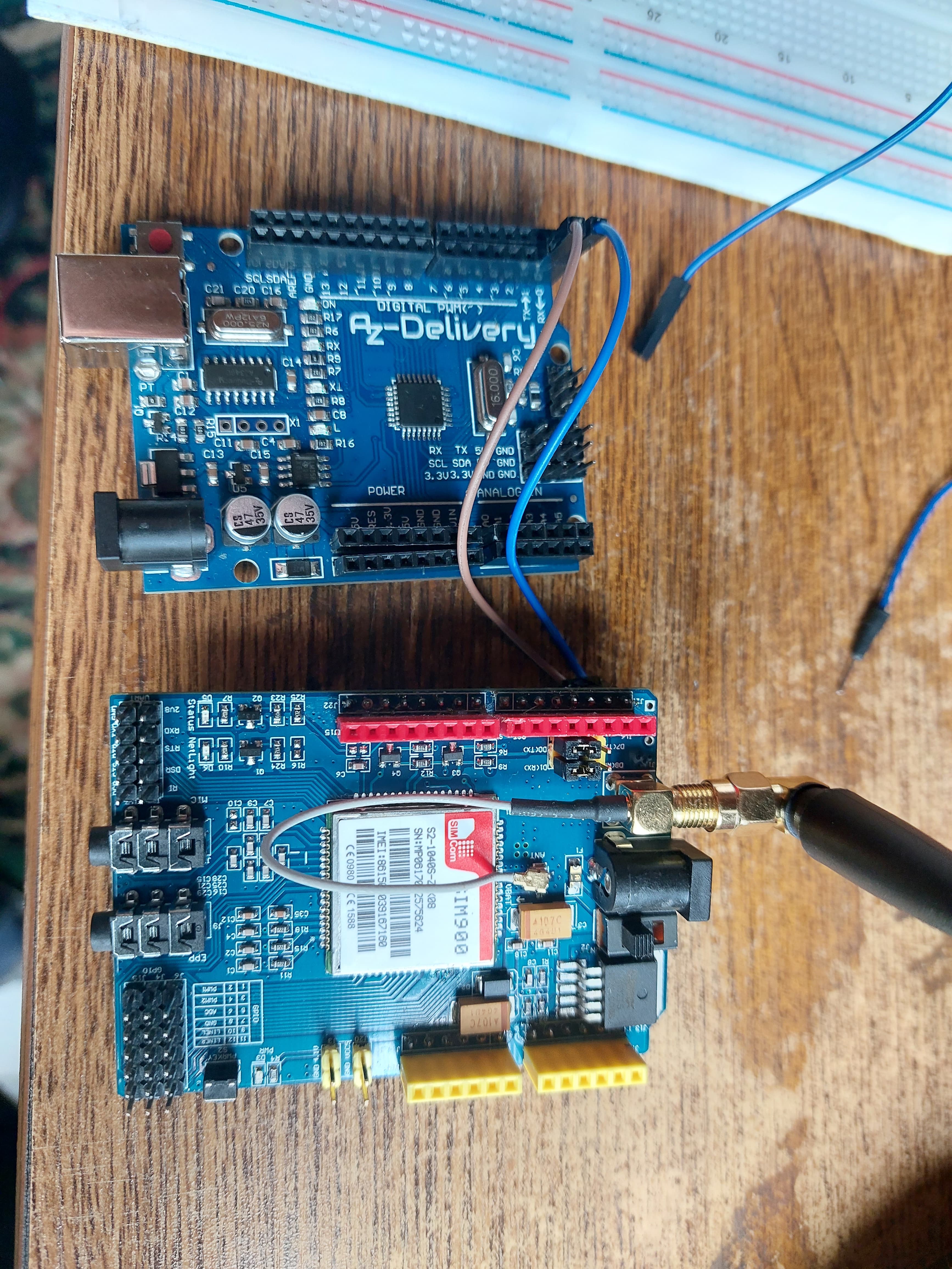
@xfpd Wiring and also the power supply. I used in first case rx and tx from the UNO, now I'm using 7 and 8. At this moment I'm only sending messages, later I like to receive messages also, but at this moment I don't need it.