Hello
I have Simcom SIM900a GSM (SIM900 (SIM900A) Mini DEV Board v3.9.2) and I am interfacing it with Arduino UNO.
I have no idea how to connect SIM900a to Arduino UNO.
What I did now is:

I connect the following Pin from above Image to:
5 to: GND (Digital GND near Pin 13)
6 to: 5V of Arduio
2 to: GND of Arduino near 5V
3 to: Digital Pin 0 of Arduino (RX)
4 to: Digital Pin 1 of Arduino (TX)
1 to: (No idea)
From Picture option 7, 8, 9 are not connected to anything.
Can you please guide me am I doing right?
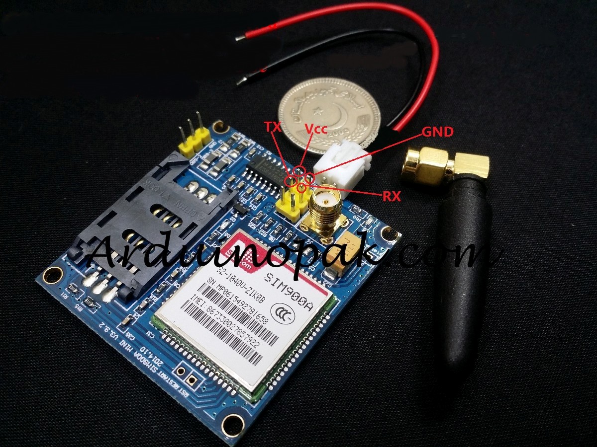
I am getting hard time to find out what is TX and RX in my SIM900a module as it is not written there.
My SIM900a looks like this:
http://upsats.com/Content/Product/img/Product/Large/SIM900V4-G36-37C.jpg (Schematics given)
SIM900 (SIM900A) Mini DEV Board - ElectroDragon
When I upload sketch of:
Example > GSM > TestModem:
I got this output from Serial Monitor:
Starting modem test...ERROR, no modem answer.
Checking IMEI...Modem's IMEI: 0
Reseting Modem... Modem is functioning properly: IMEI: 0