I have a small project for a client...we need to build a scrolling signboard that displays 4-5 messages, and also cycles/displays the current time. We need to program it into the fixture we're building, and then ship the fixture out to the site location and run automatically. (I'm having the PCBs and LED assemblies custom made)
Is there an arduino hardware/software package that comes to mind immediately? Part numbers would help greatly.
you could easily build one and program an lcd screen to display the messages and have a real time clock within the circuit to keep the time. what sort of messages will be displayed?
Did you check the Arduino examples for programming an LCD? I believe there are functions that allow the text to scroll left and right. Also for the clock, you may need an external timer circuit, see this link.
I've got a scrolling message board using four 8x8 LED matrixes and a duemilanove for a controller (but could be any arduino, a little promini, or a standalone microcontroller), add a battery backed RTC chip/module and it can query the RTC for time & display that. I have a 7 tall x 5 wide font, so it can have 5+ letters displayed as they scroll across.
Connect to a PC, program in a message, save to EEPROM. Am adapting the code to store the message as chacter #s in EEPROM (vs font definition) so up to 1022 character messages could be stored.
I know I'm not the first to do this, and I'm sure commercial versions of scrolling sign boards are available also.
This is easily adapted to accept serial messages from whereever & display/store them.
We cannot use a standard/stock signboard, as the PCB and LED assembly needs to contour to the models we're building. We're having flexible circuit boards custom built.
I'm mainly interested in knowing what the best control unit would be that incorporates the time function. I'm assuming I need to buy external time keeping hardware and inputting it into an arduino?
Simple DS1307 modules with battery backup would work, such as the "chronodot" from sparkfun.com or adafruit.com, or just google it. uC's can be had in quite small leadless packages. A ATMega1284P-MU and 5 current limit resistors could drive that 5x20 display, have 2 pins for I2C comm's with the RTC, and leave 5 pins free for buttons to set the date/time, advance to next message or change modes, whatever.
more flexible fonts scrollable column by column?
4 x MAX7219 with caps & resistor per device as shown on datasheet http://datasheets.maximintegrated.com/en/ds/MAX7219-MAX7221.pdf
Can use the same display 5x7 display, take into account the smaller size as you send it data
or, 4 x 8x8 LED MATRIX, common cathode on rows, common anode on columns
What we need the display to do:
-Display scrolling current time
-Display scrolling text (I think there will be 4-5 different messages that cycle through)
-The LED lighting matrix is 5high X 20wide. 100 LEDs total (or groups that look like single LEDs)
-Dimensions are roughly 38"w X 8"h for the 6' version and 53"w X 12"h for the 10' version
-The LED signboard needs to contour around the inside of the face of the part and sit close to the subsurface
I've contacted the company that makes the flex PCBs in the real FuelBand; however, we just got disappointing news that they may not be able to meet our deadline (11/26)
The lighting in the prototype we built is static. We plan to 'drop out' the remaining diode graphics around the "FUEL" in order to place LEDs behind them.
I think I need to clarify the scope of the project...
I guess so!
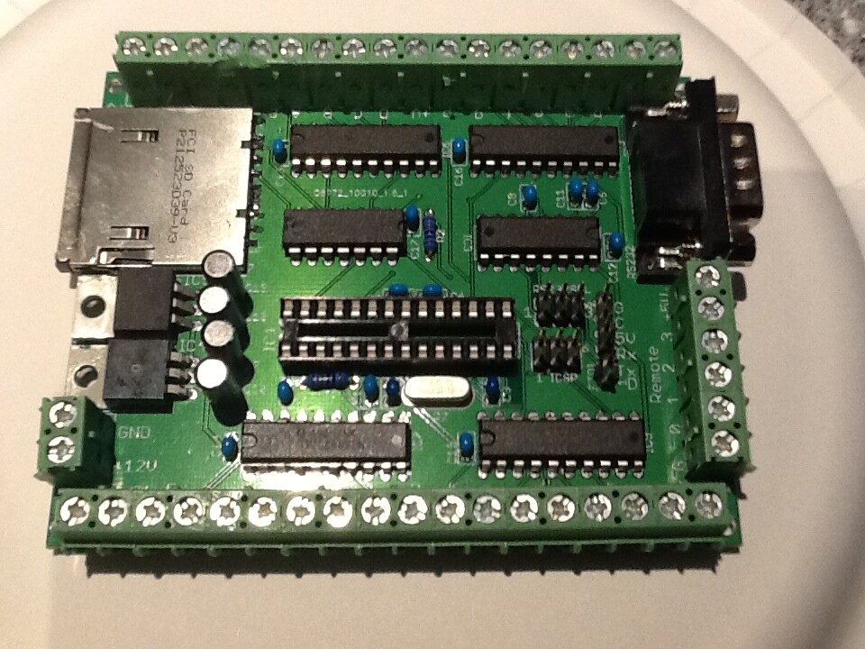
In this case, I'd suggest a board like this, 5 P-channel MOSFETs, 5 gate pullup resistors, and 5 current limit resistors.
The board has 32 bits of high voltage, high current sink drivers.
Figure you'll have 2-3 LEDs at each location.
Connect the LED "string" cathodes from each column to a current sink, and drive each row from the transistor, supplying current from a 9-12V source. P-channel MOSFET is turned on by gate being pulled low. Pullup resistor turns the gate off.
Multiplex by driving the anodes from the MOSFETs, then sinking 1 cathode.
Repeat 20 times, do it at fast rate so Persistence of Vision makes them all seem on as needed.
-The LED display in our fixture will be comprised of a field of 5H x 20W LED assemblies or single diodes
-The sign board will need to scroll messages and time
Will the Uno support this need?
Also, which RTC is best integrated with an Arduino?
Yes, if the LEDs need only 5 V and if you have shift registers to make up the other 20 outputs for the columns.
That's why I suggested a board like the one I posted with 4 high current shift registers. You can multiplex 5 times faster bu writing all 5 anodes at once and sinking the entire column.
So all the stuff I listed previously, plus 3 TPIC6B595 shift registers from avnet.com.
Drive anodes,sink cathode.
drive anodes, sink next cathode.
repeat.
Use millis() to check when its time to move to the next column.
Hey Gang,
I programmed up one my cards with 10 (of 12) shift registers, and a 2nd card with 10 more shift registers (no uC), and sent my wife out to WA to install them in Ian's display.
They made a back panel and installed some kind of 12V car LED with current limit resistor/mount/3' leads per segment, connected them to the board, and voila!
Run the movie...