I want to make a clock project. The description of my project is as follows: There will be 1 LED to show each hour, the LED corresponding to the hour the time is at that moment will be on. There will be two 7 segment LED displays as minute indicators and the minutes will be shown there.
I have 1 Arduino Uno, 1 solderless breadboard, connection cables and resistors.
I have no training in electronics. I'm trying to figure it out by researching, but I need help.
I need help with coding and connections.
Is there anyone who can help?
Thank you.
Start with a blink sketch to practice driving a single LED with your Arduino. Take it from there. Whenever you get stuck , feel free to ask specific questions. Plenty of us will be happy to help, but you need to get started first.
Thank you for your interest. I started that point, i wrote the code and managed to blink 1 LED continuously at 1 second intervals. The rest seemed complicated to me.
So there will be one led or... 12..or .24...?
Is it presenting time like a wall clock or it's counting something?
Google for Arduino seven segment clock. There will be several hundred thousand to look at and learn from.
Pick one. Build it except leave off the two seven segment displays that do the hours digits.
Half done.
Use the code's variable that holds the hour, and how your work is only to figure out how to use a number between 1 and 12, or indeed 0 and 23, to illuminate one of twelve (or 24) LEDs.
If you use an Arduino board with enough i/o pins, this will be a lesser challenge than also having to figure out how to get 24 LEDs hooked up.
UNO based projects are usually easily moved to a Mega.
Or: use smart LEDs, also known as neopixels, for the hours. One spare pin can control dozens of LEDs, and in fact makes turning one on and the rest off very simple.
I hope this informs and energizes your further researches.
a7
Good! Now add a second LED. Make that blink as well. How did that go?
I want to use this as a wall clock
There will be 12 LEDs, not 24.
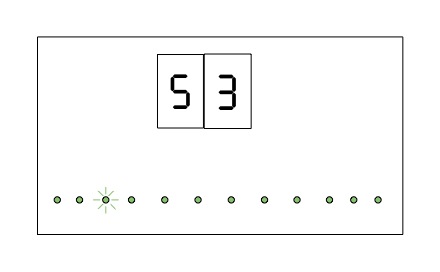
it will look like this. At 3:53 the LEDs will look like this.
1 Like
Do you have the two 7-segment displays? If yes, are they common anode or common cathode?
Start by counting the required pins. I suspect that that is 12 (for the LEDS) plus 16 (or 18 with dots) for the 2 7-segment displays. Your Uno has 20 IO pins but for development you can't use pins 0 and 1 so that leaves 18 pins.
The trick is to use multiplexing. You can control your 12 LEDs with 7 pins as shown below using a matrix. Because only one LED will be on at a time (you will need to guarantee that in software), you can get away with one resistor per block of 4 LEDs. This will not work for the 7-segment displays (you will need a resistor per segment).
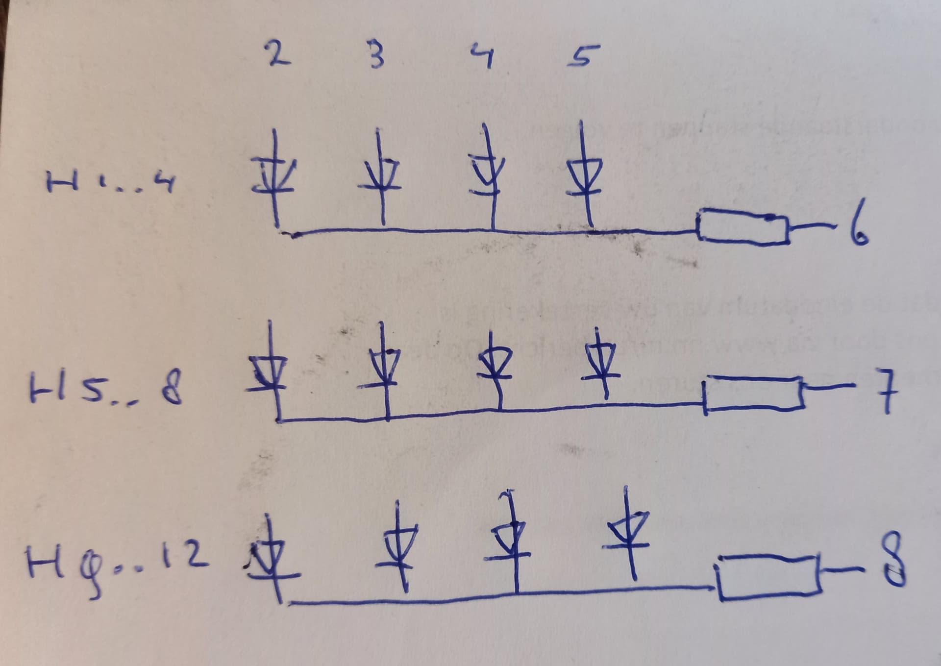
All LEDs of the first column are connected to pin 2 of the Arduino, the second column to pin 3 of the Arduino etc. So that is 4 pins. For each row of LEDs you use one pin. That makes the total 7.
In software, you can make all pins output using pinMode(); pins 6, 7 and 8 need to be made HIGH using digitalWrite(). You need to do this in setup(). The LEDs will be off.
If you want to indicate an hour, your ALWAYS first set pins 2 to 5 LOW and pins 6 to 8 HIGH using digitalWrite().
Next, if you want to indicate e.g. one o'clock, you make pin 2 HIGH and pin 6 LOW using digitalWrite(). Or if you want to indicate 11 o'clock you make pin 4 HIGH and pin 8 LOW.
For your 7-segment display, you use a similar approach. However each segment needs its own resistor. It will require 7 plus 2 pins or, with dots included, 8 plus 2 pins
Be careful
The safe current through an Arduino pin is 20 mA. The safe current through an Arduino port is 100 mA (that is 100 mA for pins 0..7, 100 mA for pins 8..13 and 100 mA for pins A0..A5). The total current through the processor's Vcc/GND is 200 mA.
Notes:
- A row in the LED design above is a common cathode design.
- You can also make use of pinMode() (instead of digitalWrite()) on pins 6 to 8 to enable a row; in that case there is no need to make the pins HIGH or LOW. pinMode(somePin, INPUT) will disable (switch off) the row, pinMode(somePin, OUTPUT) will enable (switch on) the row.
2 Likes
Do I need RTC module for this project?
You could do it with just millis() but the time will deviate a little more every day. An RTC module is advisable.
I haven't purchased the displays yet. Should I buy anode or cathode? Does it matter? I can also buy anode or cathode
I don't know, I doubt it matters too much. Have a look at existing projects on the web as @alto777 suggested in post #5. Pick one, build it, analyse the code and adjust to your needs.
If you don't use RTC, make sure you have arduinos usb easily accessible. Not just for deviation, but also blackout will reset your time. Or add some buttons to set/adjust time.
I give my vote for neopixels, it's easier to read in the dark if you have all the leds slightly visible instead of one glowing in darkness.
Don't… buy a bunch of parts, then try to work out how to write your program. Plan your development so as to postpone spending money, else you risk wasting it.
You can work on the sketch, and get it nearly 100 percent working, by building your circuit and taking small steps with the code without any real hardware:
If you are ready to write a sketch like this, or indeed in any position to succeed whilst heavily borrowing from previously written projects, you will not have much trouble using the simulator. I dare say it's almost intuitive, certainly no harder than learning how to use the IDE.
So it's still find a project you like and build it without too much change. Slavishly simulating an existing clock exactly as presented is best.
Then buy the parts, and start working on the inevitable challenges which will be getting real circuitry to function correctly - one thing you'll be sure of is that your problems will be hardware related, as you have proof in the wokwi that the code works.
Somewhere along that path you will start having the confidence and ability to get into changes to the code so it, and the clock which is your goal, will start to be yours.
a7
Thank you very much for the nice information you shared. I will try it and share the results here.
The most appropriate method to adjust the time and ensure minimum time deviation is to use the RTC module, right?
1 Like
Yes, rtc with battery.
I personally would spend that same money of rtc module to purchase esp8266 or esp32 and get time from internet (NTP) and use arduino for some other project that doesn't need real time.
1 Like
The first question is, is this an assignment or school work ? The reason to get that clear is that such assignments usually have quite concrete requirements or constraints, sometimes with a specific teaching goal in mind which may otherwise not appear logical, about what components you can use and how the end result should look.
Anyway, assuming that you want to achieve this with little more than an Arduino, a display, some leds and resistors, then multiplexing is the only way to go. This has already been said in post #8. If the 7 segment display is a single unit (as opposed to two separate single digit units) you'd anyway need to multiplex the display.
With those constraints, I'd suggest dividing the display elements into 4 groups.
- seven segment digit 1 ( common cathode)
- seven segment digit 2 ( common cathode)
- led group 1 (hours 1 to 8 inclusive)
- led group 2 (hours 9 to 12 inclusive)
The multiplexing cycle would then be a repetition of:
- display digit 1 for say 4ms.
- display digit 2 for say 4ms.
- display a led from group 1 for 4 ms (if the hour is between 1 and 8)
- display a led from group 2 for 4 ms (if the hour is between 9 and 12)
with this scheme you'd need only 12 arduino pins. With an additional 4 NPN transistors (but no extra Arduino pins), you could probably improve the brightness of the 7 segment displays.
Using the Wokwi simulator, again already suggested, you could test it all online for free. Having said that, I'm hoping that Wokwi nicely handles persistence of vision effects like multiplexing.
excellent point.
Also with Neopixels, you do things with color like have different colors for AM vs PM.
--- bill
1. Check if this dagram (Fig-1) helps you. You have very much shortage of digital pins; so, multiplexing is a logical decision. Other posters may have better proposals.
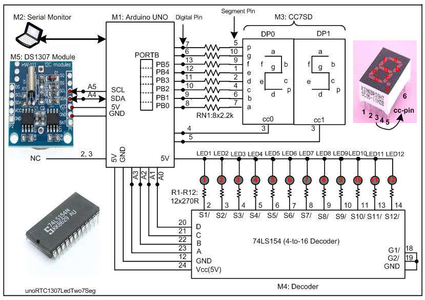
Figure-1:
2. Coding?
Before you start the coding, check that the hardware is working. Follow this SSS (Start with Small Step) Methdology that will lead you coming up with a working project.
(1) Place only the DP0 display unit on the breadboard. Make connection as per Fig-1. Write codes to show 2 on this display. Do you want codes?
(2) Place DP1 disaply unit side-by-side of DP0. You short togeter the identical segment pins (Pin-7 of DP0 with Pin-7 of DP1 and son on... except the cc-pins) to build multiplexed display unit. Write codes to show 2 on DP0 and 5 on DP1 simultaneosly. Do you want codes?
Test Codes/Sketch:
byte ccCode[] = {0x5B, 0x6D}; //cc-code for 2 and 5

void setup()
{
  for (int i = 4; i < 14; i++)
  {
    pinMode(i, OUTPUT);
  }
}

void loop()
{
  for (int i = 0; i < 2; i++)
  {
    byte x = 0b11111111;   //0b means base 2 (binary); to activate cc-pin of display devices
    bitClear(x, i);         //x = 0b11111110; Bit-0 will be sent at DPin-A0 of display to see 2
    //------------------------------------------------------------
    byte y = ccCode[i];         //cc-code of 2 and then 5
    PORTB = y;              //PORTB accepts lower 6-bit and puts on DPins:13-8
    bool m = bitRead(y, 6);
    digitalWrite(6, m);             //y6 is put on DPin-6
    digitalWrite(7, bitRead(y, 7)); //y7 is put on DPin-7
    //-----------------------------------------------------------
    digitalWrite(4, bitRead(x, 0));//DP0 is ON and then OFF in the  next pass
    digitalWrite(5, bitRead(x, 1));//DP1 is ON and then OFF
    //------------------------------------------------------------
    delay(5); //time delay for the digit to remain ON for a while so that eye can remember it
  }
}
3. Next what.......???
(1) Place all 12 LEDs on breadboard along with series resistors on the breadbord. Make 5V connection as per Fig-1. Check the healthy conditions of th LEDs by shorting their grounds (just for a while) one-by-one.
(2) Place 74LS154 decoder on the breadboard. Connect it with LEDs and UNO as per Fig-1. Write codes to activate the LEDs as per following Truth Table: (Do you want codes?)
Input On A3 A2 A1 A0                 Which LED to be turned On?
0001                                 only LED1
0010                                 only LED2
...........................
1100                                 only LED12
Test Codes/Sketch:
void setup()
{
  for (int i = 14; i < 18; i++)
  {
    pinMode(i, OUTPUT);
  }
}

void loop()
{
  for (byte i = 1; i < 13; i++)
  {
    digitalWrite(A0, bitRead(i, 0));
    digitalWrite(A1, bitRead(i, 1));
    digitalWrite(A2, bitRead(i, 2));
    digitalWrite(A3, bitRead(i, 3));
    delay(500);  //test interval
  }
}
4. Connect DS1307 RTC Module with UNO as per Fig-1.
Upload the following sketch and check that the Serial Monitor shows the time of the day correctly. (you need to install RTClib.h Library which is ttached with this post.)
RTClib-master.zip (54.2 KB)
sketch:
#include <Wire.h>
#include "RTClib.h"
RTC_DS1307 rtc;
DateTime myDT;
char daysOfTheWeek[7][12] = {"Sunday", "Monday", "Tuesday", "Wednesday", "Thursday", "Friday", "Saturday"};
byte lastReadSecond = 0;

void setup ()
{
  Serial.begin(9600);
  Wire.begin();

  Wire.beginTransmission(0x68);
  byte busStatus = Wire.endTransmission();
  if (busStatus != 0)
  {
    Serial.println("RTC is not present.");
    while (true);
  }
  Serial.println("RTC is present.");

  rtc.begin();
  rtc.adjust(DateTime(F(__DATE__), F(__TIME__)));//taking current time from PC
  // rtc.adjust(DateTime(2021, 12, 31, 01, 59, 57));//set date-time manualy:yr,mo,dy,hr,mn,sec
}

void loop ()
{
  myDT = rtc.now();
  if (lastReadSecond != myDT.second())//wait 1-sec as long as they are equal = 1s has not gones
  {
    showTimeDate();//1-sec has e;apsed; show time and date
  }
}

void showTimeDate()
{
  //update to the new second
  myDT = rtc.now();
  lastReadSecond = myDT.second();
  //------------------------------
  Serial.print(myDT.year(), DEC);
  Serial.print('/');
  //-----------------------------
  Serial.print(myDT.month(), DEC);
  Serial.print('/');
  Serial.print(myDT.day(), DEC);
  Serial.print(" (");
  Serial.print(daysOfTheWeek[myDT.dayOfTheWeek()]);
  Serial.print(") ");
  //-----------------------------
  byte myHour = myDT.hour();
 // myHour = myHour - 12;
  if (myHour < 10)
  {
    Serial.print('0');  //show leading zero
  }
  Serial.print(myHour, DEC);
  Serial.print(':');
  //-----------------------------
  byte myMin = myDT.minute();
  if (myMin < 10)
  {
    Serial.print('0');  //show leading zero
  }
  Serial.print(myMin, DEC);
  Serial.print(':');
  //--------------------------
  byte mySec = myDT.second();
  if (mySec < 10)
  {
    Serial.print('0');  //show leading zero
  }
  Serial.print(mySec, DEC);
  //----------------------------
  Serial.println();
}
5. Combine all the above fragmented codes/ sketches to make single working sketch.
... pending